ESP8266 Which module to choose?
In principle, any of the modules Wireless ESP8266 can be programmed using the languages that are available for them (also any IDE) so The choice depends mainly on the hardware implementation.. The most relevant nuance that could be made to this would be, in any case, the amount of memory available.
Although initially some modules were closely linked to certain languages or development environments, the clearest example of this is NodeMCU and lua language, it is currently relatively easy to use any of the available ones with any module.

The regulations of the site (country) where a device containing the ESP8266 wifi module It is surely the most restrictive when designing equipment that must be approved or authorized for sale. In such cases, The first step is to discard those that do not comply with the corresponding regulations (which luckily will rarely be on sale) or verify the approval of the module that has been chosen. If the series manufactured is large enough, the components will surely be used directly in the circuit design (and not a module) and the process would then be the usual one to obtain the corresponding marketing permits.
Before looking at the list of objective data to choose your own option, allow me to explain what my recommendations are for each scenario and explain why they are so.
Whether it is to be programmed in Moon as if not, the more complete solution, which does not require other components, perfect, for example, for a microcontroller programming course in which networks (Wireless) are involved, as in the case of the Internet of Things (IoT), it is NodeMCU. No need for an adapter USB to connect to the computer, it fits into a breadboard (protoboard or breadboard) or can be easily used with Dupont type connectors. More than a module, it is a development board comparable, for example, to a board Arduino.

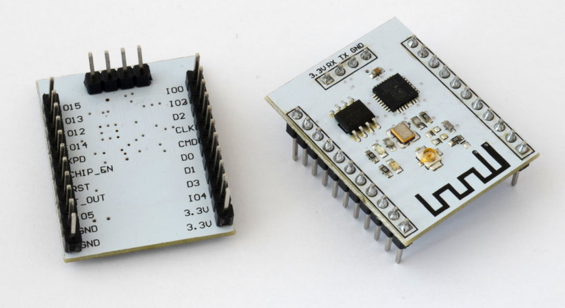
If in your laboratory or workshop it is not a problem to have an adapter USB-UART, ESP-201 AI Thinker It is a cheap version of the development board NodeMCU. It is designed to be used with Dupont type connectors rather than a breadboard; In fact, the version that is sold with the pins soldered to the board usually has one of the strips so that it cannot be inserted into a breadboard unless it is removed and welded to the opposite surface. The labeling on the temples is also not very friendly: part is on the front and part is on the back for some excellent reason that I don't know.
When it is necessary to develop an application that requires a good amount of memory, more than the usual 4 Mbit, a special version of the ESP8266, the module ESP-12F AI Thinker, which has a flash memory 32 Mbit (in addition to 96 Kbytes of RAM) and it has an excellent price, the cheapest I have found with that memory.
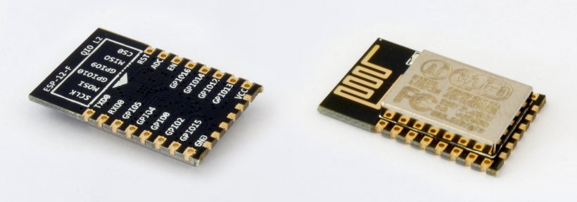
Of the 32 pins available in the package QFN Only 17 are input-output (excluding the antenna connection and the external oscillator) and of them only two, GPIO4 and GPIO5, are exclusively assigned as GPIO, since the others share a function and you must choose whether they are used, for example, for serial communications or for generic digital input-output.
So none of the modules that include the SoC ESP8266 they may have plenty of ports GPIO But since the ESP-03 version, several models of modules have appeared with more pins, and the corresponding functions available. These new modules, especially The ESP-07, the ESP-12 and most of those that have followed it, allow more easily to create circuits in which the ESP8266 not only takes care of communications Wireless but it is also the microcontroller that manages the device.
In order to be able to comfortably use the same module that will be included in the final circuit in tests, there are plates on whose surface to solder the module and that have connections for pins with the standard separation of one breadboard (one tenth of an inch).
Some of these boards include circuitry to convert the power and communications voltage levels between 3,3V and 5V so that they can also communicate with devices (or a µC) that work with that voltage.
As this type of accessory was initially designed for the modules ESP8266 ESP-07, which do not have connections on the opposite side of the antenna, it will be necessary to do without them in the newer models, such as the ESP-12E, ESP-12F, ESP-13..., connect them manually (with a cable in top) or design our own adapter board also with our own extra circuitry design to convert serial level, power, add port expanders GPIO…If you are not sure how to do it, in previous blog articles you can find some tricks to how to pin out a surface mount component like these modules that use the ESP8266.

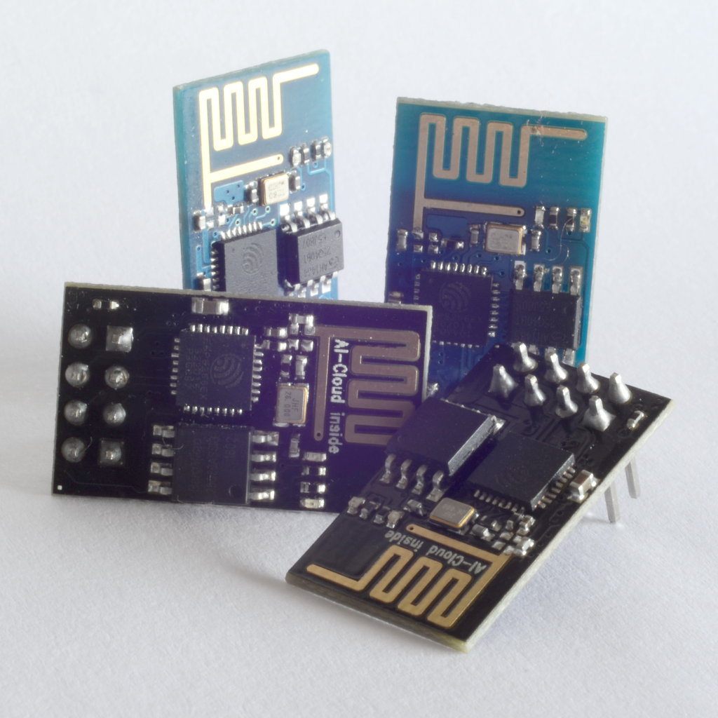
If in the assembly there is already a MCU, that is, the ESP8266 is not the microcontroller main device, the first version of the module, the ESP-01, is perfectly functional and unbeatable in price, especially if lots of several modules are purchased (when only one module is purchased, it will hardly exceed €1 difference with other models).

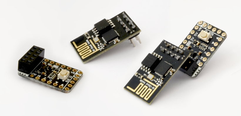
To solve the problem of the arrangement of the pins in the ESP-01 module when using it in a breadboard (protoboard or breadboard), you can use an accessory like the one in the images below, which also resolves the voltage differences that exist when used, for example, with the plates Arduino of the series powered at 5 V. In a more artisanal way, you can use one of the Tricks for connecting a module with a double pin strip to a breadboard.
Another advantage of accessories like the one shown in the images below is that they have a button (almost always), a switch or a jumper to load new firmware into the flash memory of the ESP8266 Wi-Fi SoC.
To use the ESP8266 in more specific conditions, with little space on the mounting plate, when it is necessary to have an external antenna, in situations where interference is present... you will need to refine a little more; To do so, I hope you find the following list of features helpful. I have used the company's series of modules as a reference AI Thinker which is the most complete and I have added the development board NodeMCU because it seems to me that it is the most popular.
-
ESP-01


Dimensions: 14,30mm × 24,80mm
: 1Mbit-->
Local: 8 pins between power and GPIO
Antena printed on the PCB
Unshielded
Food: 3,3V
To be precise, the newer versions include the ESP8266EX and the primitives the initial model of the ESP8266 (without EX). Although it is already difficult to find the oldest one, it is important to be careful when choosing the module to opt for the modern version.
-
ESP-02


Dimensions: 14,20mm × 14,20mm
: 1Mbit-->
Local: 8 surface connections (it is possible to solder 0,1 “pins)
Without antenna on the board but with a connector for external antenna
Unshielded
Food: 3,3V
-
ESP-03


Dimensions: 17,30mm × 12,10mm
: 1Mbit-->
Local: 14 surface connections on both long sides
Antena ceramic type
Unshielded
Food: 3,3V
-
ESP-04


Dimensions: 14,70mm × 12,10mm
: 1Mbit-->
Local: 14 surface connections on both long sides
Without antenna
shielded
Food: 3,3V
-
ESP-05


Dimensions: 14,20mm × 14,20mm
: 1Mbit-->
Local: 8 pins spaced a tenth of an inch apart on a single strip
Without antenna on board but with a connector for an external antenna
shielded
Food: 3,3V
-
ESP-06
: 17,50mm × 14,50mm -->Dimensions: 14,20mm × 14,70mm

Local: 12 connections under the plate
Without antenna
shielded
Food: 3,3V
-
ESP-07


Dimensions: 20,00mm × 16,00mm
: 1Mbit-->
Local: 16 surface connections on the long sides of the board
Antena ceramic u connector for external antenna
shielded
Food: 3,3V
-
ESP-08
: 18,00mm × 16,00mm (original version)-->Dimensions: 17,00mm × 16,00mm

Local: 16 surface connections on the long sides of the board
Without antenna
shielded
Food: 3,3V
-
ESP-09


Dimensions: 10,00mm × 10,00mm
: 1Mbit-->
Local: 18 connections under the board (6 of which go to ground)
Without antenna
Unshielded
Food: 3,3V
-
ESP-10


Dimensions: 14,20mm × 10,00mm
: 1Mbit-->
Local: 5 surface connections on one of the smaller sides
Without antenna
Unshielded
Food: 3,3V
-
ESP-11


Dimensions: 17,30mm × 12,10mm
: 1Mbit-->
Local: 8 surface connections on the side opposite the antenna
Antena ceramics
shielded
Food: 3,3V
-
ESP-12


Dimensions: 24,00mm × 16,00mm
: 1Mbit-->
Local: 16 surface connections arranged on the two long sides
Antena printed on the PCB
shielded
Food: 3,3V
-
ESP-12-E — ESP-12-F


Dimensions: 24,00mm × 16,00mm
: 1Mbit-->
Local: 22 surface connections arranged on three sides (8+8+6)
Antena printed on the PCB
shielded
Food: 3,3V
-
ESP-13
: 17,50mm × 13,50mm -->Dimensions: 18,00mm × 20,00mm

Local: 18 surface connections located on the two smaller sides
Antena printed on the PCB
shielded
Food: 3,3V
-
ESP-14


Includes a STM8 which is responsible for controlling the ESP8266 through AT orders
Dimensions: 24,30mm × 16,20mm
Local: 22 surface connections arranged on three sides (8+8+6)
Antena printed on the PCB
shielded
Food: 3,3V
-
ESP-WROOM


Dimensions: 18,00mm × 20,00mm
Local: 18 surface connections arranged on the long sides
Antena printed on the PCB
shielded
Food: 3,3V
-
NodeMCU


Based on ESP-12
Dimensions: 30,85mm × 47,35mm
Local: 30 pins spaced one tenth of an inch apart and USB
Antena printed on the PCB
shielded
Food: 3,3V and 5V
User and programming buttons (flash)
-
ESP-201


Dimensions: 26,00mm × 33,50mm
Local: 26 pins separated by a tenth of an inch and distributed in two strips of 11 on each side (which fit into a breadboard) and 4 perpendicular ones that, being soldered on the same side, are not possible to use on a breadboard.
Antena printed on the board and connector for an external antenna. You must choose between one option or the other by unsoldering a jumper (a 0 Ω resistor, by default it uses the external connector so most ESP-201 boards are sold with a small (sort of) antenna. Some older versions have the Antenna connector poorly soldered (turned 180°) and needs to be repositioned or the (external) antenna is useless.
Unshielded
Food: 3,3V
Other modules or development boards that incorporate the ESP8266
Neither more nor less than due to the extraordinary difference in the base price, which is increased by heavy shipping costs, in southern Europe the excellent plates of Adafruit or SparkFun and I suspect that except in North America they will have a difficult time competing with their Chinese counterparts. The alternatives that can be seen here are those of the house WeMos (which also comes from China) and those of Olimex, which comes from Europe and has excellent quality.
La D1 mini pro de WeMos It is a development board comparable to the NodeMCU, since it has a connector USB, can be used in a breadboard, can be powered at 5V, has a reset button, 4MB of flash memory…although in a smaller format since it has 16 pins at a tenth of an inch.
There are many modules with sensors and actuators that can be connected very easily to be used with the WeMos D1 mini pro, a bit in the style of the "shields" of Arduino. Although I have not found a complete kit, something similar will surely be marketed and, among other things due to price, it would be a very good alternative for a computer programming classroom. microcontrollers.
Olimex markets two products based on ESP8266: The MOD-WIFI-ESP8266 and MOD-WIFI-ESP8266-DEV, which are, as their prosaic names suggest, a module (10 pins) and a development board (22 pins that also fit into a breadboard). Both devices have 2 MB of flash memory and an antenna printed on the circuit board but easily allow the addition of an external antenna. Olimex It also offers a couple of boards to test with the development version, but due to their price-components they are not very competitive compared to other generic modules.
The series of products Adafruit which include the SoC ESP8266 It is made up of the plate HUZZAH ESP8266 breakout and the plate Feather HUZZAH (with ESP8266 Wi-Fi). The first is your option for development and the second, although quite versatile, is designed mainly for production, as suggested by its (more or less standard) connection to an external battery, which on the board HUZZAH ESP8266 breakout It's just a pin. Furthermore, in the development option, you can find both a reset button, also present in the production one, and another programming button that the boards Feather HUZZAH not include. The production board also has a connector USB
Both products Adafruit They can be used with pins one-tenth of an inch apart and have 26 connectors on the board case Adafruit HUZZAH ESP8266 breakout and 32 connectors on the board Adafruit Feather HUZZAH. Both are based on the ESP-12 module, so, except for the characteristics of the circuit in which it is available (such as the battery connection), the features are the same as that of this device.
The house SparkFun markets four products based on the SoC Wireless ESP8266. On the one hand, it offers the shield for Arduino SparkFun WiFi Shield whose main characteristic is precisely that: being able to be easily arranged on a arduino board.
Moreover, SparkFun also has the plate Blynk Board, whose main objective is to develop products for mobile phones as an entry option to the Internet of Things. Its connectors are quite easy to use, even by users who are not used to assembling electronic components: they can be connected with alligator clips as well as in a breadboard (protoboard or breadboard) and has vertical connectors with guides for the sensors as well as a connection USB. There are several sets of sensors for testing and it is sold with a subscription to a kind of cloud for applications developed with this device.
The options of SparkFun that will surely be more interesting to developers close to electronics are those of the Thing series: the plate ESP8266 Thing for holding and plate ESP8266 Thing – Dev Board, for development. One of the most notable differences between them is the possibility of comfortably powering the production version with a battery. Both have a switch (I don't remember any other plate ESP8266 have it), connection USB, 20 spaces (10+10) for one-tenth-inch pins and a connector for an external antenna.
Of course, there are many more development or application boards that use the ESP8266 but, in general, they focus on adding value by integrating other components and above all providing development options, especially to use the cloud, as is the case of Blynk Board de SparkFun o ESpresso Lite designed by espert and that distributes Cytron.


Post Comment