How to Pin a Surface Mount Component
Some electronic components are alternatively presented for surface mounting (SMD, SMT or SMC) or through hole (through hole); On other occasions there is only a version in one format or another, either due to mechanical or geometric needs or due to commercial intention.
For testing (and sometimes prototyping) it is much easier to use components with pins to connect cables or to insert into a breadboard (breadboard) but it may happen that you have many units of components in SMD version, although there is also its through hole version, bought in a very cheap lot or remains of another assembly, or it may also be that there is only the version for surface mounting.
If in doubt, the most appropriate thing would be to make a small printed circuit board (PCB) with which to build a module with pins with the surface components, but that takes time and it is cumbersome to dust off the insolator and prepare the liquids if you do not plan to do some more bearing. This is where this trick comes in: pinning a surface component compadre style.
Broadly, there are two ways to do it; directly on the pins, if the pitch of the pins and the size of the component allows it, or on a hole plate using some threads and of course pin strips.
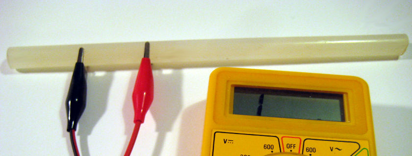
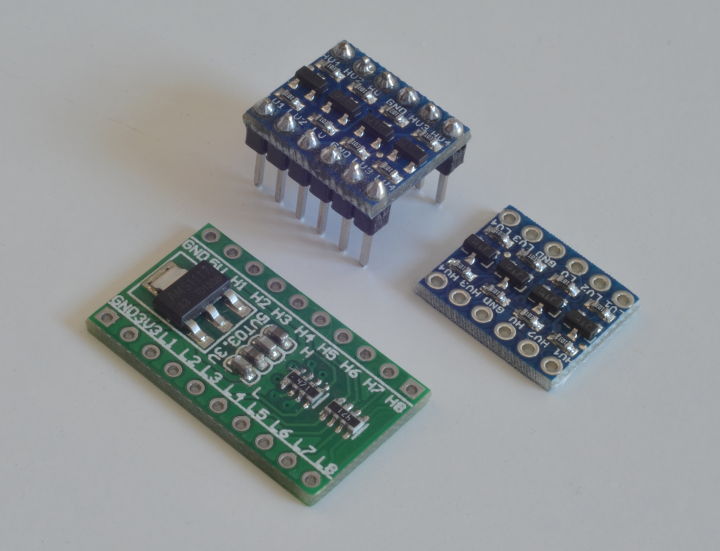
An example of the first would be this voltage regulator (a AMS1117) that converts 5 V into 3.3 V. Having a lot of surface mount components available, it was best to put them to use (they were very happy to be useful) instead of buying new regulators to do some testing on the fly.
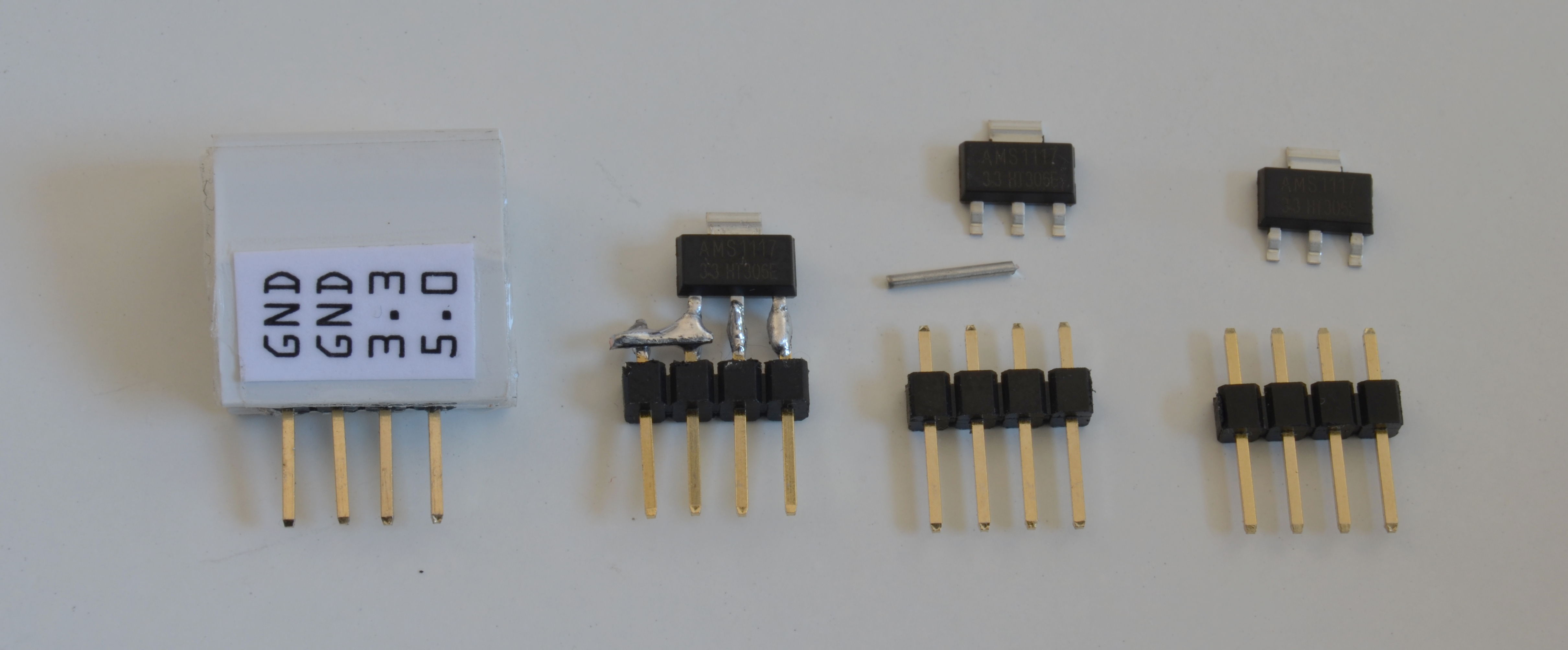
Since the separation of the terminals is almost like the size of the pins, by first soldering the central one and compensating the ones on the sides with a little tin, it is done.
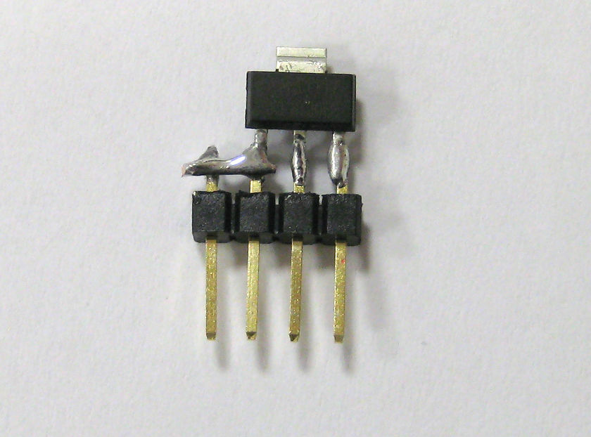
In addition, a bridge has been added to these so that there are two ground pins and it is more comfortable to use it for testing by connecting it with cables in addition to a breadboard.
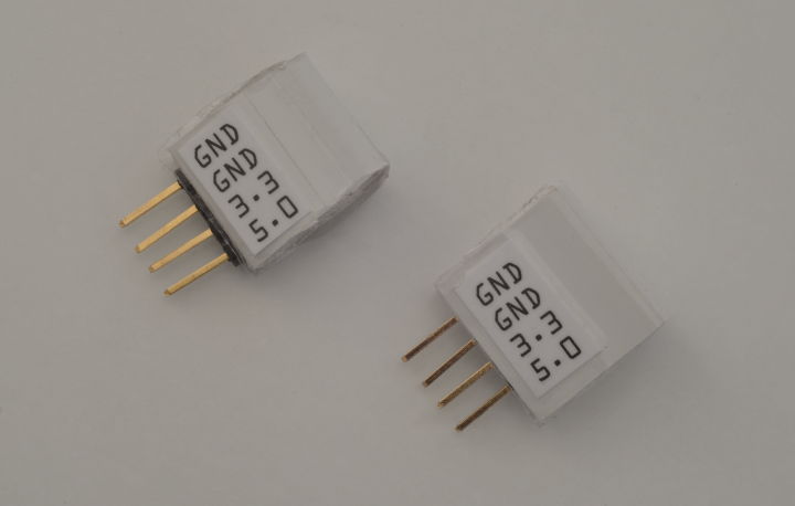
To make it easier to use, it has been covered with a binding profile and the terminals have been labeled since they are now hidden. The open end of the profile has been glued to the plastic part of the pin strip and the entire thing has been filled with silicone. Be very careful with silicone, you must make sure that it is not conductive before using it or the invention may become unusable.
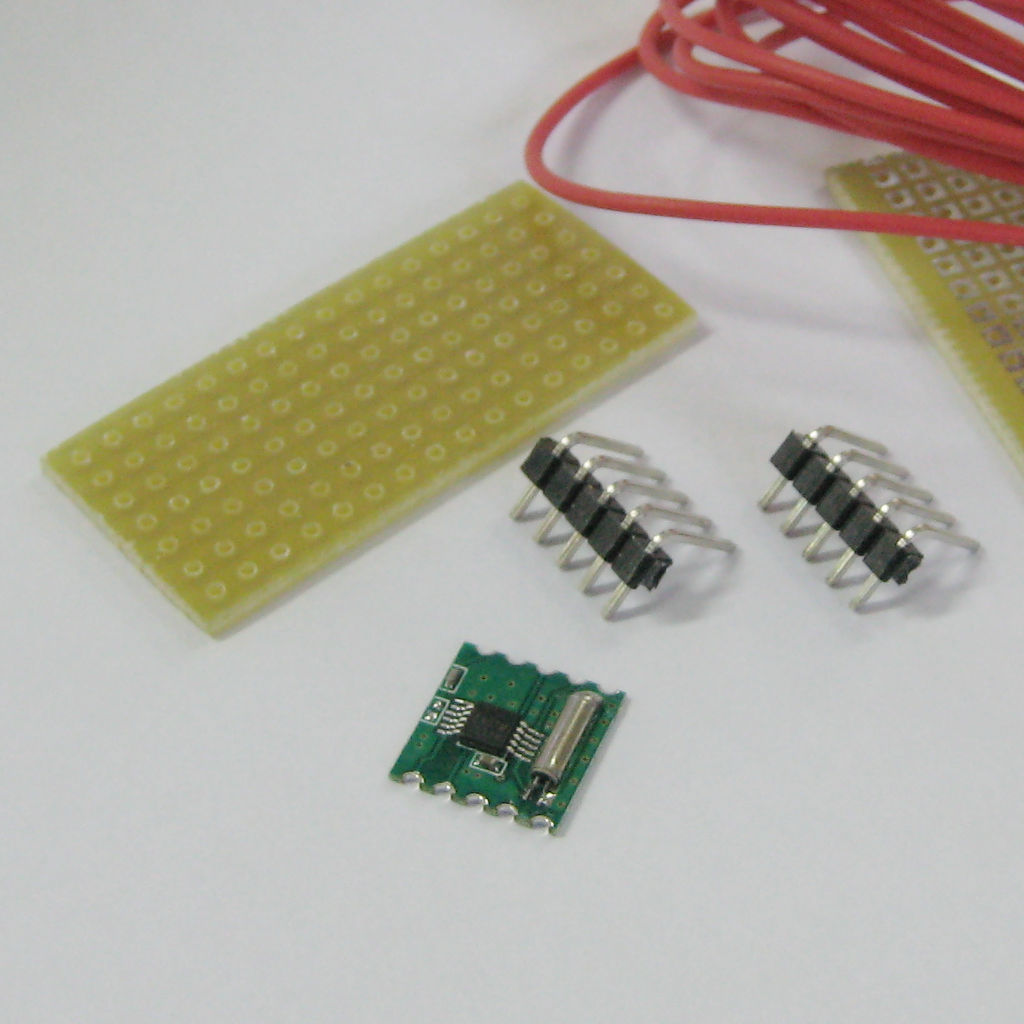
An example of a homemade module could be those made with these radio boards that add the minimum circuitry necessary to make the integrated ones work (a large TEA5767 and a small RDA5807M). As the format of the terminals is a little larger than the separation of the pins needs some trap and a hole plate.
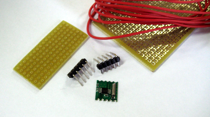
The idea is very simple, it involves joining the pins that are placed at the ends with the corresponding terminals using cables soldered to each other.
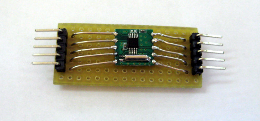
Firstly, the possibility of using only rigid cable was tested, but the joint is not strong enough and has the added disadvantage of being really uncomfortable to handle, which for testing can be torture. So it finally ended up on a hole plate. Since the cable is very rigid, it stays up a little but it is little problem compared to the alternative.

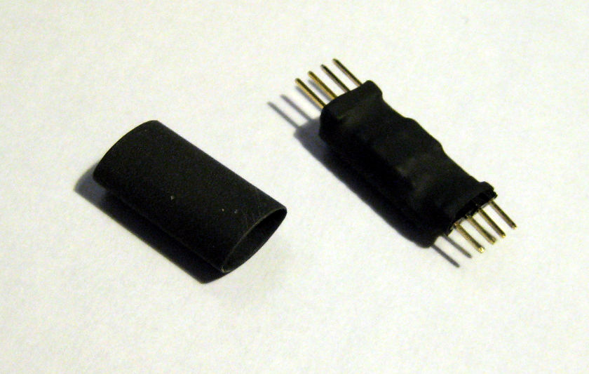
To complete it, it can be shrink-wrapped with transparent plastic or protected with a heat-shrinkable cover as has been done with this other homemade module. It may be a good idea to protect it once you verify that it works. In this case it does not need silicone so there is no need to use it, furthermore, it is possible to reuse it when the tests are finished, even in the prototype, it unsolders very well.
By the way, you don't have to get obsessed either, remember that this is a trick to save time and/or reuse boring components that you have lying around. There is a corresponding version of almost everything in a module for testing without the need for soldering. In the photo below you can see a couple of different modules for converting the voltage level, for example for communications between devices (like an Arduino Uno and an HC-05 or HC-06 Bluetooth module)


Post Comment