I2C temperature sensor LM75
Operating principle
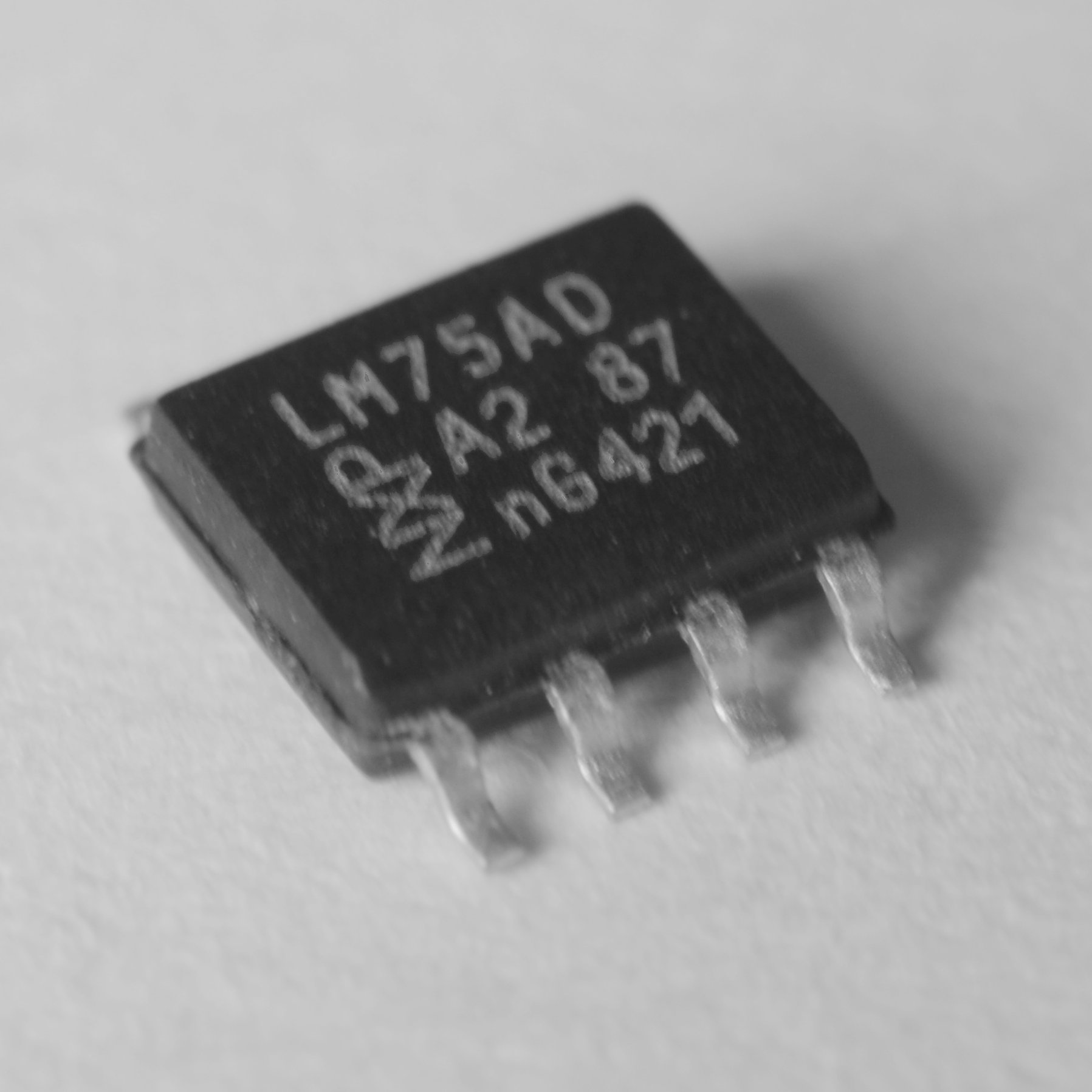
El IC LM75 is a silicon semiconductor bandgap temperature sensor.
In semiconductors, the forbidden band It is the energy zone of the electrons that cannot be increased with an increase in the electric field as there are no states available to move more quickly. This forbidden band is included between the valence band (lower energy) and the driving band (higher energy). Thermal excitation (the increase in temperature, for the purposes we are interested in) can cause some electrons to acquire enough energy to pass into the driving band.
As explained in the previous article about the electronic temperature measurement, in metals, although the number of carriers does not depend on temperature (all electrons are always available), their mobility is affected by temperature, so that the resistance in metals increases with temperature due to the decrease of the speed of the electrons due to the increase in their thermal agitation and the scattering of electrons it produces.
In the case of semiconductors, due to the presence of this forbidden band The number of carriers does depend on the temperature (depending on the Fermi–Dirac distribution) causing conductivity to increase with temperature. In semiconductors, increasing temperature produces an increase in resistance but also produces a (further) increase in conductivity.
The silicon semiconductor bandgap temperature sensors, as is the case of the LM75, work according to this principle, allowing the temperature to be determined by quantifying its influence on the voltage in a silicon diode.
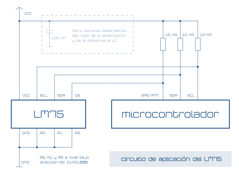
LM75 Hardware Components
The LM75 also has a analog-digital converter by Sigma-Delta modulation which is responsible for obtaining the numerical (digital) value of the temperature, a value that is subsequently stored (every 100 ms) in one of its registers from which it can be read via the bus I2C.
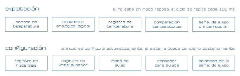
In addition to the register that contains the measured temperature, the LM75 has a register in which a maximum temperature can be stored as well as a comparator that is capable of generating a signal if the measured temperature exceeds that stored in this second register. In order not to launch the warning again until the measured temperature drops below a certain level, a third register allows storing a value for the temperature of hysteresis.
The configuration of the LM75 operation is stored in a fourth register with which the conditions under which the warning is generated, the way of launching this warning signal (interruption mode or comparison mode) as well as the activation of the device (mode) are determined. normal operation or low consumption) among other parameters.
Technical specifications and implementation of the LM75
The range of temperatures that the LM75 is capable of measuring varies from −55 °C to +125 °C and the numerical resolution is 0.125 °C although the precision is only ±2 °C in the best case, when the temperature is between −25 °C and +100 °C and an accuracy of ±3 °C with the most extreme temperatures, between −55 °C and +125 °C.
The implementation (hardware) of the LM75 in a circuit is very simple, it does not need more components than the resistors pull-up of the bus I2C and can be powered with a voltage between 2,8 V and 5,5 V. In the same bus I2C Up to eight LM75 thermometers can be arranged by configuring their address with the three pins A0, A1 and A2 at high or low level, as is usual in these cases.
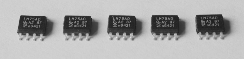
On the other hand, the use of the LM75 as a probe is uncomfortable due to the packages in which it is presented, TSSOP (TSSOP8) or SEC (SO8) and is normally used to measure ambient temperature or to measure the temperature of components arranged in the environment of the PCB in which the LM75 thermometer is located.
At startup, the LM75 is configured to detect a maximum temperature of +80°C, a temperature of hysteresis of +75 °C and the comparator operating mode, that is, the mode that emulates the operation of a thermostat: it activates the warning when the maximum temperature is reached and only if it falls below the hysteresis Regenerates the notice.
Exploitation of the LM75 from a microcontroller via the I2C bus
Thanks to the use of bus I2C The operation of the LM75 is very simple, just access the address it occupies on the bus to store or read the configuration and to obtain the value of the measured temperature.
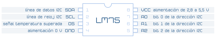
The direction I2C base of the LM75 is 0B01001XXX and is supplemented, as explained above, by the last three address bits that are set by hardware with pins A0, A1 and A2 high (value one) or low (value zero).
The LM75 as a thermometer
The register that stores the last measured temperature (TEMP) is located at address 0x00, the configuration register (CONF) is at address 0x01, the register that stores the temperature of hysteresis at address 0x02 and the maximum or over-temperature (TOS) has address 0x03. Except for the current temperature (TEMP), all of them function as read and write.
Using some code examples developed for Arduino (which has become almost a universal reference) the operation of the LM75 can be further clarified. The most basic useful example is to use the LM75 as a thermometer by reading the record of the last measured temperature.
|
1
2
3
4
5
6
7
8
9
10
11
12
13
14
15
16
17
18
19
20
21
22
23
24
25
26
|
#define DIRECCION_LM75 0B01001000 // Dirección del LM75 con A0, A1 y A2 a nivel bajo
#define TEMPERATURA_ACTUAL_LM75 0x00 // Registro que almacena la temperatura medida
//#define TIEMPO_CONVERSION_LM75 100 // El LM75 convierte la temperatura (AD) cada 100 ms así que el intervalo entre lecturas debe ser mayor.
#define TIEMPO_ENTRE_LECTURAS_DE_TEMPERATURA 3000 // Intervalo entre lecturas consecutivas de la temperatura en ms
#include <Wire.h>
int temperatura; // Valor de la temperatura actual cargado del LM75
void setup()
{
Serial.begin(9600); // Inicializar las comunicaciones serie (para mostrar en la consola el valor de la temperatura)
Wire.begin(); // Inicializar las comunicaciones I2C
}
void loop()
{
Wire.beginTransmission(DIRECCION_LM75); // Acceder al LM75 por su dirección en el bus I2C
Wire.write(TEMPERATURA_ACTUAL_LM75); // Solicitar la lectura del registro de la temperatura actual
Wire.endTransmission(); // Liberar el bus I2C
Wire.requestFrom(DIRECCION_LM75,2); // Pedir dos bytes (el valor del registro de la temperatura actual)
temperatura=(Wire.read()<<8)|Wire.read(); // Leer el primer byte, rotarlo 8 posiciones y añadir el valor del segundo byte
Wire.endTransmission(); // Liberar el bus I2C
Serial.println((float)temperatura/32/8,DEC); // Sólo son relevantes los 11 bits más significativos con una precisión de un octavo de grado (1/8 = 0.125 °C)
delay(TIEMPO_ENTRE_LECTURAS_DE_TEMPERATURA); // Esperar un poco antes de volver a leer la temperatura
}
|
The process is the usual one when working with a device I2C:
- Add the library I2C to the code with
#include <Wire.h> - Initialize the library I2C using
Wire.begin(); - Access the LM75 temperature sensor using
Wire.beginTransmission(DIRECCION_LM75) - Send the address of the registry accessed using
Wire.write(REGISTRO) - Release the bus I2C with
Wire.endTransmission() - Re-access LM75
- Request the registry value with
Wire.requestFrom(DIRECCION,CANTIDAD) - Verify that data has been received using
Wire.available() - Read the requested value
Wire.read()(as many times as bytes make it up) - Although it is not essential, when finished, release the bus I2C
In addition to the usual protocol for obtaining or storing information in the device logs using the bus I2C, to exploit the data that the LM75 provides, it is necessary to consider the format in which it internally represents the temperature.
Obtaining the value stored in the LM75 temperature records
On line 22 of the code in the previous example you can see how to load the information stored by the three temperature registers of the LM75. It uses two bytes (16 bits) of which only the 11 most significant bits are valid. To read the temperature as an integer (with the sign encoded in two's complement) the most significant byte is loaded first into a variable int de Arduino and it is rotated 8 bits to the left, leaving it in the most significant part of the int. The second byte is then read and added to the variable. int with an OR operation
Interpretation of the loaded temperature value of the LM75
In line 24 you can see how to interpret the temperature value. First of all, it is necessary to divide by 32 as an integer (rotate the relevant 11 bits without losing the sign) and divide by 8, which is the number of "steps" with which the temperature is represented (octaves of a degree) to obtain a value of type float with the corresponding decimals. Since compilers (including the toolchain de Arduino) optimize the integer division by 32, it is not necessary to preserve the sign and "manually" rotate the bits, since the operation is not (appreciably) faster.
Verify data reception from the I2C bus
Although the previous code will work without problems despite not verifying whether the data requested by the device has arrived. bus I2C, the most orthodox (and advisable) thing is to wait for the data to arrive in the appropriate number. Since the transmission speed and resistance to errors are more than sufficient, it is common to find code in which the data is simply requested and read without waiting. For the examples it is useful to do it this way since they do not distract from the main intention but for the production code it is advisable to do it as suggested in the seventh point of the list of the communication process I2C. The code in the following example highlights the recommended changes to use the LM75 in the exploitation phase.
|
1
2
3
4
5
6
7
8
9
10
11
12
13
14
15
16
17
18
19
20
21
22
23
24
25
26
27
28
29
30
31
32
33
|
#define DIRECCION_LM75 0B01001000 // Dirección del LM75 con A0, A1 y A2 a nivel bajo
#define TEMPERATURA_ACTUAL_LM75 0x00 // Registro que almacena la temperatura medida
//#define TIEMPO_CONVERSION_LM75 100 // El LM75 convierte la temperatura (AD) cada 100 ms así que el intervalo entre lecturas debe ser mayor.
#define TIEMPO_ENTRE_LECTURAS_DE_TEMPERATURA 3000 // Intervalo entre lecturas consecutivas de la temperatura en ms
#define TIMEOUT_I2C 30 // Esperar 30 ms antes de renunciar a leer el bus I2C
#include <Wire.h>
int temperatura; // Valor de la temperatura actual cargado del LM75
unsigned long cronometro_i2c; // Cronómetro para medir el tiempo de espera de la lectura del bus I2C (y cancelar la operación si se supera el máximo)
void setup()
{
Serial.begin(9600); // Inicializar las comunicaciones serie (para mostrar en la consola el valor de la temperatura)
Wire.begin(); // Inicializar las comunicaciones I2C
}
void loop()
{
Wire.beginTransmission(DIRECCION_LM75); // Acceder al LM75 por su dirección en el bus I2C
Wire.write(TEMPERATURA_ACTUAL_LM75); // Solicitar la lectura del registro de la temperatura actual
Wire.endTransmission(); // Liberar el bus I2C
Wire.requestFrom(DIRECCION_LM75,2); // Pedir dos bytes (el valor del registro de la temperatura actual)
cronometro_i2c=millis();
while(Wire.available()<2&&(unsigned long)(millis()–cronometro_i2c)>TIMEOUT_I2C); // Esperar a que lleguen dos bytes al bus I2C o pase el tiempo máximo para abandonar
if(Wire.available()==2) // Si han llegado dos bytes
{
temperatura=(Wire.read()<<8)|Wire.read(); // Leer el primer byte, rotarlo 8 posiciones y añadir el valor del segundo byte
}
Wire.endTransmission(); // Liberar el bus I2C
Serial.println((float)temperatura/32/8,DEC); // Sólo son relevantes los 11 bits más significativos con una precisión de un octavo de grado (1/8 = 0.125 °C)
delay(TIEMPO_ENTRE_LECTURAS_DE_TEMPERATURA); // Esperar un poco antes de volver a leer la temperatura
}
|
Configure the operation of the LM75
The most basic configuration of the LM75 consists of establishing the maximum temperature to generate the warning and the hysteresis, which will determine when it is deactivated and can be repeated. To configure these values you only have to store them in the corresponding registers.
Like the current temperature record, the maximum (warning) temperature and hysteresis They use two bytes but unlike the first they do not consider 11 bits (an eighth of a degree) but 9 (half a degree) so that, even if a smaller value were stored, only intervals of this resolution would be considered.
|
1
2
3
4
5
6
7
8
9
10
11
12
13
14
15
16
17
18
19
20
21
22
23
24
25
26
27
28
29
30
31
32
33
34
35
36
37
38
39
40
41
42
43
44
45
46
47
48
49
50
51
52
53
54
55
56
57
58
59
60
|
#define DIRECCION_LM75 0B01001000 // Dirección del LM75 con A0, A1 y A2 a nivel bajo
#define TEMPERATURA_ACTUAL_LM75 0x00 // Registro que almacena la temperatura medida
#define TEMPERATURA_MAXIMA_LM75 0x03 // Registro que almacena la temperatura máxima (al superarla avisa cambiando el estado del pin OS) 80 °C al inicio
#define TEMPERATURA_HISTERESIS_LM75 0x02 // Registro que almacena la temperatura por debajo de la cual la máxima vuelve a generar un cambio en el pin OS (temperatura de histéresis) 75 °C al inicio
//#define TIEMPO_CONVERSION_LM75 100 // El LM75 convierte la temperatura (AD) cada 100 ms
#define TIEMPO_ENTRE_AVISOS_DE_TEMPERATURA 3000 // Intervalo entre avisos consecutivos de exceso de temperatura en ms
#define TIMEOUT_I2C 30 // Esperar 30 ms antes de renunciar a leer el bus I2C
#define TEMPERATURA_AVISO 32.5 // Avisar a los 32.5 °C (Solamente se consideran 9 bits, es decir, medios grados)
#define TEMPERATURA_HISTERESIS 31.0 // No volver a avisar (a los 32.5 °C) hasta que no se baje a los 31.0 °C
#define PIN_AVISO_LM75 2 // Pin de Arduino al que se conecta la salida OS del LM75
#include <Wire.h> // Cargar la librería de las comunicaciones I2C
int temperatura; // Valor de la temperatura actual cargado del LM75
unsigned long cronometro_i2c; // Cronómetro para medir el tiempo de espera de la lectura del bus I2C (y cancelar la operación si se supera el máximo)
unsigned long cronometro_avisos=0; // Cronómetro para controlar que se avise del exceso de temperatura a un intervalo máximo (como máximo cada TIEMPO_ENTRE_AVISOS_DE_TEMPERATURA)
void setup()
{
pinMode(PIN_AVISO_LM75,INPUT); // Usar como entrada el pin de Arduino al que se conecta la salida OS del LM75
Serial.begin(9600); // Inicializar las comunicaciones serie
Wire.begin(); // Inicializar las comunicaciones I2C
//Configurar la temperatura de aviso
Wire.beginTransmission(DIRECCION_LM75); // Iniciar la comunicación con el LM75
Wire.write(TEMPERATURA_MAXIMA_LM75); // Acceder al registro que almacena la temperatura máxima (temperatura de aviso)
Wire.write((byte)((int)(TEMPERATURA_AVISO*8.0)>>3)); // Desplazar 5 bits a la izquierda y 8 a la derecha
Wire.write((byte)((int)(TEMPERATURA_AVISO*8.0)<<5)); // Desplazar 5 bits a la izquierda
Wire.endTransmission(); // Liberar el bus I2C
//Configurar la temperatura de histéresis
Wire.beginTransmission(DIRECCION_LM75); // Iniciar la comunicación con el LM75
Wire.write(TEMPERATURA_HISTERESIS_LM75); // Acceder a la temperatura de histéresis
Wire.write((byte)((int)(TEMPERATURA_HISTERESIS*8.0)>>3)); // Desplazar 5 bits a la izquierda y 8 a la derecha
Wire.write((byte)((int)(TEMPERATURA_HISTERESIS*8.0)<<5)); // Desplazar 5 bits a la izquierda
Wire.endTransmission(); // Liberar el bus I2C
// El aviso se activará cuando la temperatura sea TEMPERATURA_AVISO o superior
// y no se desactivará hasta que sea TEMPERATURA_HISTERESIS o inferior
}
void loop()
{
if(!digitalRead(PIN_AVISO_LM75)) // Si la señal OS del LM75 está a nivel bajo (polaridad por defecto del aviso)
{
if((millis()–cronometro_avisos)>TIEMPO_ENTRE_AVISOS_DE_TEMPERATURA) // Si ha transcurrido el tiempo entre avisos (además de estar activa la señal)
{
cronometro_avisos=millis(); // Reiniciar el cronómetro de aviso de la temperatura
Wire.beginTransmission(DIRECCION_LM75); // Acceder al LM75 por su dirección en el bus I2C
Wire.write(TEMPERATURA_ACTUAL_LM75); // Solicitar la lectura del registro de la temperatura actual
Wire.endTransmission(); // Liberar el bus I2C
Wire.requestFrom(DIRECCION_LM75,2); // Pedir dos bytes (el valor del registro de la temperatura actual)
cronometro_i2c=millis(); // Iniciar el cronómetro que controla si ha pasado el tiempo máximo de espera de recepción de datos desde el bus I2C
while(Wire.available()<2&&(unsigned long)(millis()–cronometro_i2c)>TIMEOUT_I2C); // Esperar a que lleguen dos bytes al bus I2C o pase el tiempo máximo para abandonar
if(Wire.available()==2) // Si han llegado dos bytes
{
temperatura=(Wire.read()<< 8)|Wire.read(); // Leer el primer byte, rotarlo 8 posiciones y añadir el valor del segundo byte
Serial.println((float)temperatura/32/8,DEC); // Sólo son relevantes los 11 bits más significativos con una precisión de un octavo de grado (1/8 = 0.125 °C)
}
Wire.endTransmission(); // Liberar el bus I2C
}
}
}
|
Since in the previous code only the configuration of the temperatures related to the warning is changed, the rest of the operation corresponds to the default configuration.
In this default configuration there are two characteristics that are relevant, firstly the warning mode, by default what is called "thermostat mode" which consists of activating the warning when the maximum temperature (or warning) is reached and not deactivating it until lower to the temperature of hysteresis. The alternative is the "interrupt mode", in which the signal is activated when it exceeds the maximum or when it reaches a value lower than that of the hysteresis and is reset by reading any record, normally the current temperature.
The second characteristic is that the warning signal is activated at a low level, that is, the OS pin is at a high level until the maximum warning temperature is reached. Since the polarity of the warning signal (the level at which it is activated) is configurable, in some simple installations it will be enough to use this signal (hardware) to exploit the LM75, for example, connecting or disconnecting a fan when the system reaches a certain temperature.
It is also possible to configure the operation of the LM75 so that it does not warn immediately after reaching the warning temperature but does so after several incidents. This behavior is very useful when working at the temperature limit or when it varies very quickly. The LM75 can be configured to warn after exceeding the maximum temperature one, two, four or six times.
In the configuration register there is also a bit to deactivate ("turn off") the LM75 and enter a low consumption mode, which is exited by changing this bit again or simply when reading the next register.
|
1
2
3
4
5
6
7
8
9
10
11
12
13
14
15
16
17
18
19
20
21
22
23
24
25
26
27
28
29
30
31
32
33
34
35
36
37
38
39
40
41
42
43
44
45
46
47
48
49
50
51
52
53
54
55
56
57
58
59
60
61
62
63
64
65
66
67
68
69
70
71
72
73
74
75
76
77
78
79
80
81
82
83
84
|
#define DIRECCION_LM75 0B01001000 // Dirección del LM75 con A0, A1 y A2 a nivel bajo
#define TEMPERATURA_ACTUAL_LM75 0x00 // Registro que almacena la temperatura medida
#define TEMPERATURA_MAXIMA_LM75 0x03 // Registro que almacena la temperatura máxima (al superarla avisa cambiando el estado del pin OS) 80 °C al inicio
#define TEMPERATURA_HISTERESIS_LM75 0x02 // Registro que almacena la temperatura por debajo de la cual la máxima vuelve a generar un cambio en el pin OS (temperatura de histéresis) 75 °C al inicio
#define CONFIGURACION_LM75 0x01 // Registro del LM75 que almacena la configuración. El valor por defecto es cero
#define ENCENDER_LM75 0B00000000 // Encender el LM75 almacenando este valor (OR el resto) en el registro de configuración
#define APAGAR_LM75 0B00000001 // Apagar el LM75 (modo de bajo consumo) almacenando el valoren el registro de configuración
#define AVISO_LM75_COMPARAR 0B00000000 // Activo cuando se supera la temperatura máxima inactivo cuando la temperatura es menor que la de histéresis (modo termostato)
#define AVISO_LM75_INTERRUPCION 0B00000010 // Activo cuando se supera la temperatura máxima. Se resetea al leer el valor. No se volverá a activar hasta que no se alcance (primero) la de histéresis
#define AVISAR_LM75_BAJO 0B00000000 // Establece el nivel bajo en el pin OS cuando se supere la temperatura máxima
#define AVISAR_LM75_ALTO 0B00000100 // Establece el nivel alto en el pin OS cuando se supere la temperatura máxima
#define AVISAR_LM75_A_1 0B00000000 // Avisar cuando se supere una vez la temperatura (con riesgo de que un error producido por ruido en la conversión lance un aviso incorrecto)
#define AVISAR_LM75_A_2 0B00001000 // Avisar de temperatura superada cuando se mida dos veces
#define AVISAR_LM75_A_4 0B00010000 // Avisar de temperatura superada cuando se mida cuatro veces
#define AVISAR_LM75_A_6 0B00011000 // Avisar de temperatura superada cuando se mida seis veces
//#define TIEMPO_CONVERSION_LM75 100 // El LM75 convierte la temperatura (AD) cada 100 ms
#define TIEMPO_ENTRE_LECTURAS_DE_TEMPERATURA 2000 // Intervalo entre lecturas de la temperatura en ms
#define TIMEOUT_I2C 30 // Esperar 30 ms antes de renunciar a leer el bus I2C
#define TEMPERATURA_AVISO 32.5 // Avisar a los 32.5 °C (Solamente se consideran 9 bits, es decir, medios grados)
#define TEMPERATURA_HISTERESIS 31.0 // No volver a avisar (a los 32.5 °C) hasta que no se baje a los 31.0 °C
#define PIN_AVISO_LM75 7 // Pin de Arduino al que se conecta la salida OS del LM75
#include <Wire.h> // Cargar la librería de las comunicaciones I2C
int temperatura; // Valor de la temperatura actual cargado del LM75
unsigned long cronometro_i2c; // Cronómetro para medir el tiempo de espera de la lectura del bus I2C (y cancelar la operación si se supera el máximo)
unsigned long cronometro_avisos=0; // Cronómetro para controlar que se avise del exceso de temperatura a un intervalo máximo (como máximo cada TIEMPO_ENTRE_AVISOS_DE_TEMPERATURA)
void setup()
{
pinMode(PIN_AVISO_LM75,INPUT); // Usar como entrada el pin de Arduino al que se conecta la salida OS del LM75
Serial.begin(9600); // Inicializar las comunicaciones serie
Wire.begin(); // Inicializar las comunicaciones I2C
// El aviso se activará, a nivel alto (AVISAR_LM75_ALTO), cuando la temperatura sea TEMPERATURA_AVISO o superior cuatro veces consecutivas (AVISAR_LM75_A_4, que vale 0B00010000)
// y no se desactivará hasta que sea TEMPERATURA_HISTERESIS o inferior
// Configurar la temperatura de aviso
Wire.beginTransmission(DIRECCION_LM75); // Iniciar la comunicación con el LM75
Wire.write(TEMPERATURA_MAXIMA_LM75); // Acceder al registro que almacena la temperatura máxima (temperatura de aviso)
Wire.write((byte)((int)(TEMPERATURA_AVISO*8.0)>>3)); // Desplazar 5 bits a la izquierda y 8 a la derecha
Wire.write((byte)((int)(TEMPERATURA_AVISO*8.0)<<5)); // Desplazar 5 bits a la izquierda
Wire.endTransmission(); // Liberar el bus I2C
// Configurar la temperatura de histéresis
Wire.beginTransmission(DIRECCION_LM75); // Iniciar la comunicación con el LM75
Wire.write(TEMPERATURA_HISTERESIS_LM75); // Acceder a la temperatura de histéresis
Wire.write((byte)((int)(TEMPERATURA_HISTERESIS*8.0)>>3)); // Desplazar 5 bits a la izquierda y 8 a la derecha
Wire.write((byte)((int)(TEMPERATURA_HISTERESIS*8.0)<<5)); // Desplazar 5 bits a la izquierda
Wire.endTransmission(); // Liberar el bus I2C
// Configurar el número de veces que debe superarse la temperatura para generar un aviso y la polaridad del aviso
Wire.beginTransmission(DIRECCION_LM75); // Iniciar la comunicación con el LM75
Wire.write(CONFIGURACION_LM75); // Acceder al registro de configuración
Wire.write(AVISAR_LM75_ALTO|AVISAR_LM75_A_4); // Componer la configuración con operaciones OR sobre los diferentes (bits) valores
Wire.endTransmission(); // Liberar el bus I2C
}
void loop()
{
if((millis()–cronometro_avisos)>TIEMPO_ENTRE_LECTURAS_DE_TEMPERATURA) // Si ha transcurrido el tiempo entre lecturas
{
cronometro_avisos=millis(); // Reiniciar el cronómetro de aviso de la temperatura
Wire.beginTransmission(DIRECCION_LM75); // Acceder al LM75 por su dirección en el bus I2C
Wire.write(TEMPERATURA_ACTUAL_LM75); // Solicitar la lectura del registro de la temperatura actual
Wire.endTransmission(); // Liberar el bus I2C
Wire.requestFrom(DIRECCION_LM75,2); // Pedir dos bytes (el valor del registro de la temperatura actual)
cronometro_i2c=millis(); // Iniciar el cronómetro que controla si ha pasado el tiempo máximo de espera de recepción de datos desde el bus I2C
while(Wire.available()<2&&(unsigned long)(millis()–cronometro_i2c)>TIMEOUT_I2C); // Esperar a que lleguen dos bytes al bus I2C o pase el tiempo máximo para abandonar
if(Wire.available()==2) // Si han llegado dos bytes
{
temperatura=(Wire.read()<<8)|Wire.read(); // Leer el primer byte, rotarlo 8 posiciones y añadir el valor del segundo byte
Serial.print(“Temperatura “);
if(digitalRead(PIN_AVISO_LM75)) // Si la señal OS del LM75 está activa (a nivel alto)
{
Serial.print(“demasiado alta”);
}
else
{
Serial.print(“correcta”);
}
Serial.print(” (“);
Serial.print((float)temperatura/32/8,DEC); // Sólo son relevantes los 11 bits más significativos con una precisión de un octavo de grado (1/8 = 0.125 °C)
Serial.println(“)”);
}
Wire.endTransmission(); // Liberar el bus I2C
}
}
|


Post Comment