Ethernet connection with the Microchip ENC28J60 integrated
The integrated ENC28J60 is a controller Ethernet with interface for SPI bus. It is designed to be used with small systems, usually based on microcontrollers.
Su SPI bus can operate at up to 20 MHz and the Ethernet connection has a maximum speed of 10 Mbit/s (10BASE T) supporting modes Duplex (Full-Duplex) and Semi-duplex (Half-Duplex) with automatic polarity detection and correction. Although 10 Mbit/s may seem like a low speed compared to the network GigaBit Ethernet which is the most common today, but it is more than enough to integrate a small microcontrolled device into a network, for example, to perform functions such as an object of IoT (Internet of Things, Internet of Things)
It operates at 3,3 V although it is tolerant to 5 V signals, making it very easy to integrate with different microcontrollers as well as work with it during prototyping or testing.

Internally includes a buffer configurable for reception/transmission, a FIFO circular for reception and direct memory access (DMA) to streamline data movement. It is capable of doing the hardware checksums and other typical communications operations Ethernet so its integration at the software level in a project is very simple.
The typical configuration requires, in addition to a 25 MHz oscillator (a crystal with its corresponding capacitors), a connector and Ethernet transformers, which are often encapsulated together with other components such as resistors or LEDs to report link and reception/reception status. transmission in a block containing the connector RJ45.

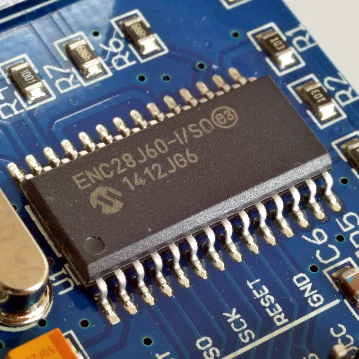
It is only manufactured for surface mount (SMT/SMD) in 28-pin packages SPDIP (a DIP with higher pin density), SSOP, SEC y QFN Therefore, to carry out tests or prototypes, we usually work with modules like those in the previous image, of which, in addition, individual units are easily available, compared to the integrated module itself, which is usually on the market in large batches.
|
|
||||||
| Vcap | → | 01 | 28 | ← | True | |
| vss | → | 02 | 27 | → | LEDA | |
| CLKOUT | ← | 03 | 26 | → | LEDB | |
| INT | ← | 04 | 25 | ← | Vddosc | |
| NC | ← | 05 | 24 | → | OSC2 | |
| SO | ← | 06 | 23 | ← | OSC1 | |
| SI | → | 07 | 22 | ← | Vssosc | |
| SCK pins can be used | → | 08 | 21 | ← | Vsspll | |
| CS | → | 09 | 20 | ← | Vddpll | |
| RESET | → | 10 | 19 | ← | Vddrx | |
| Vssrx | → | 11 | 18 | ← | Vsstx | |
| TPIN- | → | 12 | 17 | → | TPOUT+ | |
| TPIN+ | → | 13 | 16 | → | TPOUT- | |
| RBIAS | → | 14 | 15 | ← | Vddtx | |
In addition to (1) the power supply, once the integrated unit is mounted, (2) the connections will be exposed. Ethernet through the end of the connector RJ45 and for the microcontrolled part of the assembly the SPI bus (MOSI/MISO/SCLK/CS) and (3) managed directly by the microcontroller or another part of the electronic assembly can be connected INT, which can be used as WOL (Wake-On-LAN) or remote wake-up via network (Remote Wake-up), RESET and a connection to external clock CLKOUT.

As an example, to make these connections between a module with the integrated ENC28J60 and a plate Arduino The values in the following table should be followed depending on the type of plate.
| ENC28J60 | UNO Arduino | Arduino MEGA/DUE | Arduino Leonardo |
| MISO (SO) | MISO (pin 12) | MISO (pin 50) | MISO (ICSP connector) |
| MOSI (YES) | MOSI (pin 11) | MOSI (pin 51) | MOSI (ICSP connector) |
| SCK pins can be used | SCK (pin 13) | SCK (pin 52) | SCK (ICSP connector) |
| RESET | RESET | RESET | RESET |
| INT | INT0 (pin 2) | INT4 (pin 2) | INT0 (pin 2) |
| SS (CS) | SS (pin 10)* | SS (pin 53)* | pin 10* |
| Vdd (3,3V) | 3V3 | 3V3 | 3V3 |
| Vss (GND) | GND | GND | GND |
In general, the connections are those that would be expected based on what has been said (and logic) but there are some differences between the boards. In the case of Arduino Leonardo, unless the SS pin has been manually soldered on the board (it is common to add pins 22-CTS and 8-SS) pin 10 is used, which does not have this assignment, so it will need to be considered in the control software. On the other hand, it is not essential to use the "standard" pin to select (activate) the slave device but most of the Ethernet libraries to manage the integrated one expect to use that pin (and for that purpose) so they will have to be modified in case contrary and in some cases (some libraries) when the board is used Leonardo.

Another consideration that must be attended to also corresponds to the plate Leonardo and the use of the connector CPSI instead of the corresponding ones (of the side blocks) on the plate UNO Arduino


Post Comment