Basic operations on an ESP8266 wifi module from Arduino
When Espressif launched the first modules on the market Wireless with the integrated ESP8266 and firmware with which to handle it using AT commands, what we users were interested in was integrating it into assemblies with microcontrollers and the problems were reduced to knowing the (formerly) dark ESP8266 AT command table, feeding needs or ESP8266 firmware update.
Then alternatives quickly arrived to program the ESP8266 and module implementations Wireless of very different formats that raised other concerns: which ESP8266 wifi module to choose depending on the range of the different antennas (including external ones) or the physical integration of these new modules in our assemblies.
Surely, due to all these changes, emphasis may not have been placed on the most basic aspects, the most basic management of the ESP8266 wifi module. Although polarity.es You can find information on the use of the ESP8266 and there are some applications intended to explain in a generic way the operation of the ESP8266 wifi module using AT commands, especially in the article on library to make HTTP queries from Arduino with the ESP8266 wifi module, readers' impressions suggest that it would be useful to add some more basic information to help users of the ESP8266 to carry out their own implementations.
Discuss the basic operations to work with the ESP8266 and proposing generic solutions is an objective of several very different parts; To help follow the content of the article, the following index can serve as a guide:
- Control the ESP8266 wifi module from the computer through the serial port
- Update firmware with esptool
- Send orders to the module
- Receive data from the ESP8266
- Analyze the response by searching for texts in the content
- Limit the waiting time for receiving the response
- Execute a complex operation defined by multiple AT commands
Control the ESP8266 wifi module from the computer through the serial port
From a plate Arduino and using your IDE it is possible to monitor the operation of a ESP8266 wifi module, send the ESP8266 AT commands and see the answer but it is much more convenient to do it from a computer with a terminal type application.

Depending on which board Arduino used, only one hardware serial port may be available, which adds a little inconvenience to sending and receiving. Changing the communications speed is much more comfortable in a serial communications application from a computer and some motherboards. Arduino (and in some circumstances) do not support the higher speeds of serial communications well, especially 115200 baud, which is the default speed of the latest versions of the firmware.
About What program to use to monitor the ESP8266 using the serial port, there are many to choose from according to needs and preferences; lately I'm using the classic more CuteCom (the one in the screenshot above) because it is very comfortable for me to repeat certain ESP8266 wifi module AT orders in project testing.
Some recommendations have already been given here on programs that function as a serial console; For example, when talking about PuTTY for controlling UART serial devices from the computer. PuTTYIn addition to being an excellent application, it is available for most desktop operating systems. Furthermore, as PuTTY can be used to act as a console with both the serial port and the Internet protocol family (TCP/IP), including those that operate on TLS, becomes a common tool that more than repays the (little) time spent configuring it and getting used to its use.

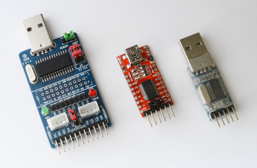
In addition to serial communications software, to connect the ESP8266 wifi module to the port USB A computer also requires a converter USB to series TTL. As in the case of software, there are several versions, from which they are only used to convert the port USB on a serial port TTL (which can be obtained from one Euro) to those that can emulate different protocols (such as SPI o I2C).
Just like a program that functions as a serial console, the hardware to communicate the computer via USB with a logic circuit (not just the ESP8266) will be a common tool in the work of a microcontrolled application developer, it is worth having it in the toolbox as soon as possible and working with it ESP8266 wifi module It is an excellent opportunity to get one.
The converter USB a UART TTL It can also be used to monitor the behavior of a circuit that uses the ESP8266, to do this, the outputs that you want to monitor are connected in series to the data input (RX) of the converter with a fast diode (the 1N4148, for example) and a resistor (2K2, for example) in parallel with each other. Such a setup works like a hardware serial sniffer.
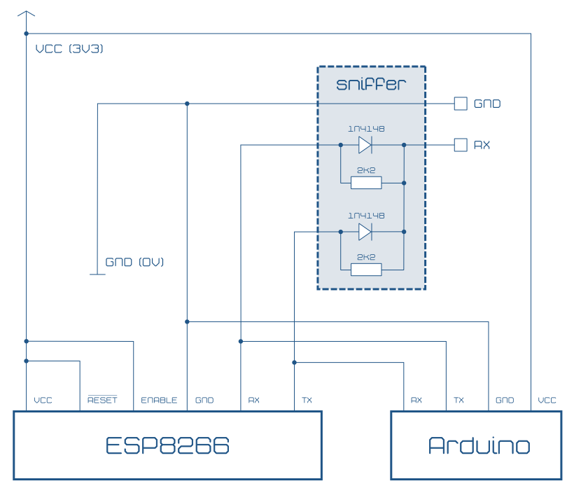
Although the sniffer in the image above is certainly rudimentary (among other things it does not have buffer) is sufficient to monitor the operation of an assembly with Arduino and ESP8266.
Removing the sniffer from the previous scheme, the schematic showing how to connect a ESP8266 wifi module to a plate Arduino. In addition to feeding it at 3V3, the reset pin and the activation pin of the integrated must be connected to a high level (enable). Of course, the RX pin of one must connect to the TX of the other.
To simplify the previous diagram, a plate has been represented Arduino powered at 3V3 and for which a voltage on the serial port is also assumed to be 3V3. If you use a microcontroller with a different signal level on the serial port (typically 5 V) will be necessary, so as not to damage the ESP8266, use a level converter like those in the diagrams below. This circuit is frequently found in many commercial off-the-shelf module implementations.

Update ESP8266 firmware
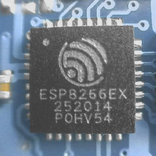
All the ESP8266 AT commands, its termination, the default speed of the module... depend on the version of the ESP8266 firmware. It is best to ensure that you have the same version in all modules and, if possible, that it is the latest version.
Unfortunately, most of the ESP8266 wifi module models They only have 4Mbit, so the latest version cannot be installed on them. The latest (official) version of firmware that can be installed on ESP8266 wifi modules with 4 Mbit (most) is 0.9.4 which includes version 0.2 of the ESP8266 AT commands.
In summary, to update the firmware you need:
-
Download the corresponding firmware version. The latest (official) version for a module with 4Mbit of memory, found in the Espressif folder on github. In the Espressif website You can download the most recent version of the firmware, but it is very important to verify that the module on which it is installed has enough memory.
-
Download the latest version of the firmware installation tool. My favorite is esptool which is written in Python, so it works on any platform. In addition to being downloaded, it can also be installed with
pip install esptool(opip2opython -m pip…). Of course, Espressif It also offers its own tool but is currently only available for Windows. -
Prepare downloaded files; unzip them in an accessible folder and, if necessary, make the tool executable esptool, in my case, since GNU / Linux, with
chmod +x esptool -
Connect the module to the computer using a converter USB UART TTL that works at 3V3 or use a level converter if it works at 5 V. In addition to the power, you will have to connect TX to RX of the converter USB UART TTL, RX to TX, GPIO0 at low level (GND) and maybe GPIO2 at high level (in my tests it has worked both connecting it at low level and disconnecting it). If the module has the GPIO15 connection free (as occurs in the ESP-12) it must be connected to a low level. RESET, which would normally be at a high level during operation, can be left unconnected or connected to a high level by means of a resistor (10K, for example), since before starting recording it may be necessary to reset the device by connecting it to a low level .
By powering up the module it will be available to update but, If a connection error is displayed, it will be necessary to reset it connecting RESET at a low level for an instant and then leaving it on air (without connecting) for the update process.
The module has half ampere consumption peaks (up to 600 mA, according to some users) so it is important to use a power supply capable of supporting this consumption, especially for updating firmware.
-
Run the tool to update the firmware. In my case, I have saved the tool and firmware documents in step 3 in the same folder, so I run from the console:
cd ~/Datos/firmwareESP8266(change to the folder containing the tool and firmware)./esptool.py --baud 115200 --port /dev/ttyUSB0 write_flash \0x00000 ./boot_v1.1.bin \0x01000 ./user1.bin \0x7C000 ./esp_init_data_default.bin \0x7E000 ./blank.bin--baudsets the speed of the ESP8266 (115200 baud in my case) and--portthe serial port it connects to (in my case, emulated, the first USB). The different documents that make up the firmware go behindwrite_flashpreceded by the address, with the user1.bin document containing the update payload.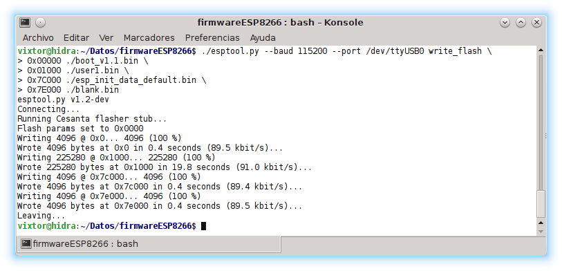
Send commands to ESP8266 wifi module
To control the ESP8266 from a computer we will have to start with configure the app for which it will be enough to ① choose the port to which the converter is connected USB UART TTL, something like /dev/USB0 in GNU/Linux and similar or something like COM6 in Windows, ② choose the speed at which the ESP8266, probably 115200 baud, ③ set 8 data bits plus one stop bit, without parity or handshake, and ④ set end of line, depending on the firmware, almost always CR+LF.


Once the application is configured (or, where appropriate, stored and selected), it is open the connection ("open device" and "open", respectively, in the screenshots of the examples above with CuteCom y PuTTY) and you can start sending orders to ESP8266.
As can be seen in the ESP8266 AT command table, the format for activating, deactivating, setting a value and referring to it is quite predictable, but in general it is not easy to remember them all and you will probably need to have it on hand to refer to it.
The way of send AT orders al ESP8266 wifi module from Arduino is very simple: ① configure communications with Serial.begin(115200); (or Serial1, Serial2… on boards with several hardware serial ports) and ② send the commands using the format Serial.print(orden+"\r\n");
|
1
2
3
4
5
6
7
8
9
10
11
12
13
14
15
16
17
18
19
20
21
|
#define PUERTO_SERIE Serial // Objeto serie que corresponde a puerto serie hardware al que está conectado el módulo wifi ESP8266
#define VELOCIDAD_ESP8266 115200 // Velocidad, en baudios, a la que está configurado el ESP8266
#define IDENTIFICADOR_WIFI “polaridad.es” // SSID (Service Set Identifier)
#define CLAVE_WIFI “54lLij1RiTn3MEd3v41C” // Clave del punto de acceso wifi al que se conecta el ESP8266
void setup()
{
PUERTO_SERIE.begin(VELOCIDAD_ESP8266);
PUERTO_SERIE.print
(
“AT+CWJAP=\””+
String(IDENTIFICADOR_WIFI)+
“\”,\””+
String(CLAVE_WIFI)+
“\”\r\n”
);
}
void loop()
{
}
|
The example above shows how to send the ESP8266 wifi module AT orders from Arduino. In this case it is illustrated AT+CWJAP, which is used to connect to an access point. This command uses as arguments the access point identifier (SSID) and the key, both in quotes, so they become an object Srtring and enclose them in quotes using the escape code (\"). To complete the order, use \r\n which corresponds to CR y LF.
To remember that the serial port is not always identified with Serial (on certain plates it can be Serial1, Serial2…) the port object used has been defined by assigning it to the macro PUERTO_SERIE. Detecting the type of board used could add a bit of intelligence to serial port selection; Later we will go over how you can find out the type of Arduino. The rest of the definitions are the usual ones that allow you to "name" the constant values to avoid repeating them (and making mistakes) and make it easier to change them.
The above example is supposed to connect the ESP8266 wifi module to the indicated access point but was it already connected before? Has the connection worked? To know this, we need to "listen" to what the ESP8266
Receive data from ESP8266 wifi module
By connecting the data sniffer explained above to the computer you can see what Arduino has sent the ESP8266 and his response. To read from Arduino and process the information in it it will be necessary to detect with Serial.available() if any data has arrived and if so load it with Serial.read(). The following example shows how to read the response from AT+CWJAP?, which will report if there is a connection to any access point.
|
1
2
3
4
5
6
7
8
9
10
11
12
13
14
15
16
17
18
|
#define PUERTO_ESP8266 Serial // Objeto serie que corresponde a puerto serie hardware al que está conectado el módulo wifi ESP8266
#define VELOCIDAD_ESP8266 115200 // Velocidad, en baudios, a la que está configurado el ESP8266
char letra_recibida;
void setup()
{
PUERTO_ESP8266.begin(VELOCIDAD_ESP8266);
PUERTO_ESP8266.print(“AT+CWJAP?\r\n”);
}
void loop()
{
while(PUERTO_ESP8266.available())
{
letra_recibida=PUERTO_ESP8266.read();
}
}
|
Like on a plate Arduino Uno (and in others) opening the serial monitor resets the program, it can be used to see in the serial console Arduino the information you send to ESP8266 as the screenshot of the image below shows.

Analyze the response sent by the ESP8266 wifi module
We have already seen how to read the information that reaches Arduino from the ESP8266. The problem you have to deal with is that you don't know when it will start to arrive, how long it will take to arrive, what length it will be... and it is not very efficient to wait for the response from the ESP8266 is received without letting the microcontroller perform other tasks in the meantime.
A simple way to manage this circumstance is iterate on the data received looking for concrete answers with which, for example, activate indicators (flags or Boolean variables) that will determine whether to continue searching in the received text and what actions should be carried out based on the information that arrives from the ESP8266. While the response arrives microcontroller can dedicate to other tasks, for example, receiving data from sensors and processing it.
Search for a text in the information received from the ESP8266
To search the text that comes from the ESP8266 can be compare each letter received with the one that corresponds to the message you are looking for. It will be necessary to use a counter (or a pointer) that points to the letter to be compared; If the character that arrives from the ESP8266 is the same as the one being examined in the message, the counter advances, if it is different it is initialized.
To know that the end has been reached, the next character of the searched message is consulted, which will be zero (\0) or the length of the message is stored to, by comparing it with the counter, know if the comparison has finished and therefore the ESP8266 wifi module has sent the wanted message.
The following example uses the command AT+CWLAP which will return a list of access points and within them one called "wifi polaridad.es" is searched. Although we have chosen to verify that the last character is zero, as the buffer It only stores the searched text and its length is known, it could also be checked if such a number of correct letters have been received. With a LED connected to pin 2 it is reported that the expected text has been found.
|
1
2
3
4
5
6
7
8
9
10
11
12
13
14
15
16
17
18
19
20
21
22
23
24
25
26
27
28
29
30
31
32
33
34
35
36
37
38
39
40
41
42
43
44
45
46
47
48
49
50
|
#if defined(ARDUINO_AVR_LEONARDO)||defined(ARDUINO_AVR_MEGA2560) /* ¿Es una placa Arduino Mega 2560 o Arduino Leonardo? */
#define SERIE Serial1 /* Si es una placa Arduino Mega 2560 o Arduino Leonardo usar Serial1 */
#else /* En este proyecto solamente uso Placas Leonardo, Mega 2560 y Uno, así que tiene que ser un Arduino Uno si llega hasta aquí */
#define SERIE Serial /* Si es una placa Arduino Uno usar Serial */
#endif
#define VELOCIDAD 115200 // Velocidad (en baudios) al que está configurado el módulo wifi ESP8266 (Cuidado con la placa utilizada, no todas o siempre son capaces de trabajar a una velocidad tan alta)
#define ORDEN “AT+CWLAP\r\n” // Buscar los puntos de acceso wifi disponibles. (Dependiendo de la versión del firmware) Las órdenes terminan en CR+LF
#define MENSAJE_BUSCADO “wifi polaridad.es” // Ver si está disponible el punto de acceso llamado “wifi polaridad.es”
#define LONGITUD_MENSAJE 18 // Se necesita guardar, al menos, 17 letras y el terminador \0
#define PIN_LED_ENCONTRADO 2 // Pin al que se conecta el LED que informa de que se ha encontrado el texto (el punto de acceso buscado está disponible)
#include <string.h> // strncpy
boolean esperando=true;
char buffer_mensaje;
char mensaje[LONGITUD_MENSAJE];
byte posicion_mensaje=0;
void setup()
{
pinMode(PIN_LED_ENCONTRADO,OUTPUT);
digitalWrite(PIN_LED_ENCONTRADO,LOW); // Apagar el LED (por ahora no se ha encontrado el mensaje)
strncpy(mensaje,MENSAJE_BUSCADO,LONGITUD_MENSAJE); // sizeof(mensaje)
SERIE.begin(VELOCIDAD); // Configurar el puerto serie de Arduino a la velocidad del ESP8266
SERIE.print(ORDEN); // Enviar la orden (consultar los puntos de acceso disponibles) al módulo wifi ESP8266
}
void loop()
{
if(esperando) // Buscará infinitamente hasta que llegue el texto esperado (y si no existe el punto de acceso nunca llegará ¡Es un ejemplo!)
{
while(SERIE.available()) // Si ha llegado algún dato por el puerto serie…
{
buffer_mensaje=SERIE.read(); // …almacenarlo en el buffer
if(buffer_mensaje==mensaje[posicion_mensaje]) // Si el dato que ha llegado es igual al que correspondería del mensaje buscado…
{
posicion_mensaje++; // Pasar a la siguiente letra del mensaje
if(mensaje[posicion_mensaje]==0) // ¿Ha terminado de analizarse todo el mensaje? (la última letra de la cadena de texto es \0)
{
esperando=false; // Si se ha terminado de analizar con éxito todo el mensaje ya no se está esperando
digitalWrite(PIN_LED_ENCONTRADO,HIGH); // Encender el LED para indicar que se ha encontrado el texto buscado
}
}
else // Si la letra que ha llegado por el puerto serie no corresponde con la buscada del mensaje…
{
posicion_mensaje=0; // …empezar desde la primera letra del texto buscado
}
}
}
}
|
In the code of the previous example you can also see a way to choose the serial port depending on the type of board Arduino used. This example assumes that you have three types of boards for the project: one Arduino Unoa Arduino Mega 2560 and a Arduino Leonardo. If you work with a Arduino Uno it will be used Serial and otherwise Serial1.
If you work with a plate Arduino Leonardo You can use the same method to stop the program and wait for the console (the serial port associated with Serial) is available.
|
1
2
3
4
5
6
7
8
9
10
11
|
#ifdef ARDUINO_AVR_LEONARDO
#define SERIE Serial1
#define ESPERA_CONSOLA while(!Serial){} /* Esperar a la consola */
#else
#define ESPERA_CONSOLA /* Si no es un Arduino Leonardo no hace falta esperar a la consola */
#ifdef ARDUINO_AVR_MEGA2560
#define SERIE Serial1
#else // En este proyecto solamente uso Placas Leonardo, Mega 2560 y Uno, así que tiene que ser un Arduino Uno si llega hasta aquí
#define SERIE Serial
#endif
#endif
|
Search various texts in the ESP8266 response
The code in the previous example is used to search for text in the information sent by the ESP8266 but the response may include different information depending on the operation. Suppose, to start with a simple case in the next example, that the text sent by the MCU ESP8266 es OK when the operation is performed correctly and ERROR Otherwise, as with the order AT+CWJAP?, which serves to verify if the ESP8266 wifi module is already connected to an access point.
|
1
2
3
4
5
6
7
8
9
10
11
12
13
14
15
16
17
18
19
20
21
22
23
24
25
26
27
28
29
30
31
32
33
34
35
36
37
38
39
40
41
42
43
44
45
46
47
48
49
50
51
52
53
54
55
56
57
58
59
60
61
62
63
64
|
#if defined(ARDUINO_AVR_LEONARDO)||defined(ARDUINO_AVR_MEGA2560) /* ¿Es una placa Arduino Mega 2560 o Arduino Leonardo? */
#define SERIE Serial1 /* Si es una placa Arduino Mega 2560 o Arduino Leonardo usar Serial1 */
#else /* En este proyecto solamente uso Placas Leonardo, Mega 2560 y Uno, así que tiene que ser un Arduino Uno si llega hasta aquí */
#define SERIE Serial /* Si es una placa Arduino Uno usar Serial */
#endif
#define VELOCIDAD 115200 // Velocidad (en baudios) al que está configurado el módulo wifi ESP8266 (Cuidado con la placa utilizada, no todas o siempre son capaces de trabajar a una velocidad tan alta)
#define ORDEN “AT+CWJAP?\r\n” // Verificar que está conectado a un punto de acceso
#define CANTIDAD_MENSAJES 2 // Se distingue entre dos mensajes: acierto y error que se identificarán con true y false
#define MENSAJE_ACIERTO “OK”
#define MENSAJE_ERROR “ERROR”
#define LONGITUD_MENSAJE 6 // Se necesita guardar, al menos, 5 letras y el terminador \0 (Un pequeño desperdicio al hacer una matriz en la que todos los elementos ocupan como el mayor. Es admisible porque son muy pocos elementos y así no se complica este ejemplo inicial)
#define PIN_LED_ACIERTO 2 // Pin al que se conecta el LED que informa del acierto
#define PIN_LED_ERROR 3 // Pin al que se conecta el LED que informa del error
#include <string.h> // strncpy
boolean esperando=true; // Todavía no se ha encontrado el final del mensaje
char buffer_mensaje; // Para almacenar la última letra cargada desde el ESP8266
byte led_estado[CANTIDAD_MENSAJES]; // Un LED (pin) para cada estado
char mensaje[CANTIDAD_MENSAJES][LONGITUD_MENSAJE]; // Mensajes de acierto y error
byte posicion_mensaje[CANTIDAD_MENSAJES]; // Un contador de posición para cada mensaje
void setup()
{
led_estado[true]=PIN_LED_ACIERTO;
led_estado[false]=PIN_LED_ERROR;
for(byte numero_mensaje=0;numero_mensaje<CANTIDAD_MENSAJES;numero_mensaje++)
{
pinMode(led_estado[numero_mensaje],OUTPUT); // Establecer el pin del LED
digitalWrite(led_estado[numero_mensaje],LOW); // Apagar el LED
posicion_mensaje[numero_mensaje]=0; // Inicializar a cero el número de letra a analizar de cada mensaje
}
strncpy(mensaje[true],MENSAJE_ACIERTO,LONGITUD_MENSAJE); // Preparar el mensaje de acierto
strncpy(mensaje[false],MENSAJE_ERROR,LONGITUD_MENSAJE); // Preparar el mensaje de error
SERIE.begin(VELOCIDAD); // Configurar el puerto serie de Arduino a la velocidad del ESP8266
SERIE.print(ORDEN); // Enviar la orden (verificar si existe conexión a un punto de acceso) al módulo wifi ESP8266
}
void loop()
{
if(esperando) // Buscará infinitamente hasta que llegue el texto esperado (y si no existe el punto de acceso nunca llegará ¡Es un ejemplo!)
{
while(SERIE.available()) // Si ha llegado algún dato por el puerto serie…
{
buffer_mensaje=SERIE.read(); // …almacenarlo en el buffer
for(byte numero_mensaje=0;numero_mensaje<CANTIDAD_MENSAJES;numero_mensaje++)
{
if(buffer_mensaje==mensaje[numero_mensaje][posicion_mensaje[numero_mensaje]]) // Si el dato que ha llegado es igual al que correspondería del mensaje buscado…
{
posicion_mensaje[numero_mensaje]++; // Pasar a la siguiente letra del mensaje
if(mensaje[numero_mensaje][posicion_mensaje[numero_mensaje]]==0) // ¿Ha terminado de analizarse todo el mensaje actual? (la última letra de la cadena de texto es \0)
{
esperando=false; // Si se ha encontrado algún mensaje y ya no se está esperando
digitalWrite(led_estado[numero_mensaje],HIGH); // Encender el LED correspondiente al mensaje encontrado
}
}
else // Si la letra que ha llegado por el puerto serie no corresponde con la buscada del mensaje…
{
posicion_mensaje[numero_mensaje]=0; // …empezar desde la primera letra del texto buscado
}
}
}
}
}
|
This new implementation of the same method, which searches for a match with several possible messages, allows you to choose between different actions depending on the response received from the ESP8266, simply turn on the LED corresponding.
Limit the time it takes to receive a response
Until now no reference has been made to a relevant issue: the maximum waiting time (timeout) before considering an operation failed. If for any reason the connection with the ESP8266 wifi module, the module with the access point, the access point with Internet or, for example, a hypothetical server is not available, the program may be blocked at one point waiting indefinitely, so a response will have to be articulated to such circumstances. The maximum wait time can be configured for the entire application, usually it will be more "generous" in that case, or individual wait times can be programmed for each operation.
To check that (at least) a certain time interval has passed The "time" of the moment in which the account is started is usually subtracted from the current "time" and it is verified that the difference is greater than the desired limit. This "time" does not have to be real time, it usually corresponds to the interval that has passed since the MCU start counting time; This does not affect the program since what is interesting is elapsed time and not the absolute time.
Usually, to check if a certain interval has elapsed, an expression of the type is used:
|
1
|
(unsigned long)(millis()–milisegundos_al_empezar)>intervalo_de_tiempo
|
The variable milisegundos_al_empezar contains the value of millis() of a certain moment in the execution from which it is timed, so it is not unusual that its name refers to the word "chronometer." The variable intervalo_de_tiempo contains the maximum number of milliseconds that makes the previous expression true, that is, it represents the timeout; It is usually a constant (or a macro) and, as in the previous case, the word "TIMEOUT" often appears in its name. If you work with very short intervals you can use micros() instead of millis() (microseconds instead of milliseconds) although it is much less common and much less precise.
|
1
|
(unsigned long)(millis()–cronometro)>TIMEOUT
|
A long integer in Arduino (unsigned long) occupies 4 bytes (32 bits), so the largest value it can represent is 4294967295 (2 to the power of 32 minus one, because it starts at zero). on a plate Arduino While running continuously the millisecond counter will reset (return to zero) approximately every 50 days. When subtracting with unsigned data types the same behavior is reproduced (flipping the counter) so it is feasible to control the timeout indefinitely.
|
1
2
3
4
5
6
7
8
9
10
11
12
13
14
15
16
17
18
19
20
21
22
23
24
25
26
27
28
29
30
31
32
33
34
35
36
37
38
39
40
41
42
43
44
45
46
47
48
49
50
51
52
53
54
55
56
57
58
59
60
61
62
63
64
65
66
67
68
69
70
71
72
73
74
|
#if defined(ARDUINO_AVR_LEONARDO)||defined(ARDUINO_AVR_MEGA2560) /* ¿Es una placa Arduino Mega 2560 o Arduino Leonardo? */
#define SERIE Serial1 /* Si es una placa Arduino Mega 2560 o Arduino Leonardo usar Serial1 */
#else /* En este proyecto solamente uso Placas Leonardo, Mega 2560 y Uno, así que tiene que ser un Arduino Uno si llega hasta aquí */
#define SERIE Serial /* Si es una placa Arduino Uno usar Serial */
#endif
#define VELOCIDAD 115200 // Velocidad (en baudios) al que está configurado el módulo wifi ESP8266 (Cuidado con la placa utilizada, no todas o siempre son capaces de trabajar a una velocidad tan alta)
#define ORDEN “AT+CWJAP?\r\n” // Verificar que está conectado a un punto de acceso
#define CANTIDAD_MENSAJES 2 // Se distingue entre dos mensajes: acierto y error que se identificarán con true y false
#define MENSAJE_ACIERTO “OK”
#define MENSAJE_ERROR “ERROR”
#define LONGITUD_MENSAJE 6 // Se necesita guardar, al menos, 5 letras y el terminador \0 (Un pequeño desperdicio al hacer una matriz en la que todos los elementos ocupan como el mayor. Es admisible porque son muy pocos elementos y así no se complica este ejemplo inicial)
#define PIN_LED_ACIERTO 2 // Pin al que se conecta el LED que informa del acierto
#define PIN_LED_ERROR 3 // Pin al que se conecta el LED que informa del error
#define TIMEOUT 5000 // Espera 5 segundos la respuesta del ESP8266 (y su análisis) antes de desistir
#include <string.h> // strncpy
boolean esperando=true; // Todavía no se ha encontrado el final del mensaje
boolean encontrado=false; // Salvo que se encuentre el punto de acceso se considera que la operación ha fracasado
char buffer_mensaje; // Para almacenar la última letra cargada desde el ESP8266
byte led_estado[CANTIDAD_MENSAJES]; // Un LED (pin) para cada estado
char mensaje[CANTIDAD_MENSAJES][LONGITUD_MENSAJE]; // Mensajes de acierto y error
byte posicion_mensaje[CANTIDAD_MENSAJES]; // Un contador de posición para cada mensaje
unsigned long cronometro;
void setup()
{
led_estado[true]=PIN_LED_ACIERTO;
led_estado[false]=PIN_LED_ERROR;
for(byte numero_mensaje=0;numero_mensaje<CANTIDAD_MENSAJES;numero_mensaje++)
{
pinMode(led_estado[numero_mensaje],OUTPUT); // Establecer el pin del LED
digitalWrite(led_estado[numero_mensaje],LOW); // Apagar el LED
posicion_mensaje[numero_mensaje]=0; // Inicializar a cero el número de letra a analizar de cada mensaje
}
strncpy(mensaje[true],MENSAJE_ACIERTO,LONGITUD_MENSAJE); // Preparar el mensaje de acierto
strncpy(mensaje[false],MENSAJE_ERROR,LONGITUD_MENSAJE); // Preparar el mensaje de error
SERIE.begin(VELOCIDAD); // Configurar el puerto serie de Arduino a la velocidad del ESP8266
SERIE.print(ORDEN); // Enviar la orden (verificar si existe conexión a un punto de acceso) al módulo wifi ESP8266
cronometro=millis();
}
void loop()
{
if(esperando) // Buscará infinitamente hasta que llegue el texto esperado (y si no existe el punto de acceso nunca llegará ¡Es un ejemplo!)
{
while(SERIE.available()) // Si ha llegado algún dato por el puerto serie…
{
buffer_mensaje=SERIE.read(); // …almacenarlo en el buffer
for(byte numero_mensaje=0;numero_mensaje<CANTIDAD_MENSAJES;numero_mensaje++)
{
if(buffer_mensaje==mensaje[numero_mensaje][posicion_mensaje[numero_mensaje]]) // Si el dato que ha llegado es igual al que correspondería del mensaje buscado…
{
posicion_mensaje[numero_mensaje]++; // Pasar a la siguiente letra del mensaje
if(mensaje[numero_mensaje][posicion_mensaje[numero_mensaje]]==0) // ¿Ha terminado de analizarse todo el mensaje actual? (la última letra de la cadena de texto es \0)
{
encontrado=numero_mensaje; // (numero_mensaje!=0) Hay conexión con el punto de acceso
esperando=false; // Si se ha encontrado algún mensaje y ya no se está esperando
digitalWrite(led_estado[numero_mensaje],HIGH); // Encender el LED correspondiente al mensaje encontrado
}
}
else // Si la letra que ha llegado por el puerto serie no corresponde con la buscada del mensaje…
{
posicion_mensaje[numero_mensaje]=0; // …empezar desde la primera letra del texto buscado
}
}
}
if((unsigned long)(millis()–cronometro)>TIMEOUT&&!encontrado) // Se ha superado el tiempo de espera y no hay conexión (se ha verificado que no hay o no ha llegado respuesta)
{
digitalWrite(PIN_LED_ERROR,HIGH); // Si ha superado el tiempo de espera encender el LED de error
esperando=false;
}
}
}
|
The above code shows a very basic implementation of timeout limitation incorporating the lines marked with respect to the example that precedes it. Since the timeout verification is performed after processing the data arriving from the ESP8266 wifi module, the operation can be considered successful even if reception takes longer than the imposed waiting time.
Execute a complex operation defined by multiple AT commands
To have an example reference of the purpose of the application that exploits the ESP8266 wifi module, suppose it is store information in a database accessed through a web service to keep track of the temperature. The following code reads a sensor connected to an analog input every certain time interval, calculates the average value and, after a longer time interval, sends it to the web server (style IoT) through a request HTTP (POST, GET…).
|
1
2
3
4
5
6
7
8
9
10
11
12
13
14
15
16
17
18
19
20
21
22
23
24
25
26
27
28
29
30
31
32
33
|
#define PIN_TEMPERATURA A0 // Pin analógico al que se conecta la salida del sensor de temperatura LM35
#define INTERVALO_LECTURA_TEMPERATURA 30000 // Leer la temperatura cada 30 segundos (30*1000)
#define INTERVALO_GRABACION_TEMPERATURA 300000 // Grabar la media de la temperatura cada 5 minutos (5*60*1000)
unsigned long muestras=0; // Número de veces que se ha medido la temperatura (para calcular la media)
float temperatura; // de -55.0 °C a +150 °C | de -550 mV a +1500 mV | de 0 V a 2.050 V | analogRead*5.0/1023.0*100-55.0 -> analogRead/2.46-55.0
float media_temperaturas=0.0;
unsigned long cronometro_lectura_temperatura;
unsigned long cronometro_grabacion_temperatura;
void setup()
{
Serial.begin(9600);
cronometro_lectura_temperatura=millis();
cronometro_grabacion_temperatura=millis();
}
void loop()
{
if((unsigned long)(millis()–cronometro_lectura_temperatura)>INTERVALO_LECTURA_TEMPERATURA)
{
cronometro_lectura_temperatura=millis();
temperatura=analogRead(PIN_TEMPERATURA)/2.46–55.0;
muestras++;
media_temperaturas=(float)temperatura/(float)muestras+media_temperaturas*(float)(muestras–1)/(float)(muestras);
}
if((unsigned long)(millis()–cronometro_grabacion_temperatura)>INTERVALO_GRABACION_TEMPERATURA)
{
cronometro_grabacion_temperatura=millis();
// Aquí iría la parte del código que graba la temperatura. Para verificar el funcionamiento, en este ejemplo simplemente se muestra en la consola
Serial.println(“\nTemperatura media “+String(temperatura,DEC)+” °C (“+String((float)millis()/1000.0,DEC)+” s)\n”);
}
}
|
In this temperature recording example, a web server is accessed every five minutes. Although the availability is not particularly high, it is to be expected that the proposal would work, but if a higher recording frequency were necessary, other resources would have to be implemented, for example, a data buffer waiting to be sent, to send several when the server can attend and store them for when it is not available. If the frequency with which data needs to be recorded was even greater, other types of protocols would have to be proposed as an alternative to the HTTP or even replace TCP by UDP to be able to send most of the data at the required speed even at the cost of losing some.
The operations that make up the task to be carried out to send the temperature would be:
- Reset the wifi module
- Disconnect from the current access point (in case a default connection exists)
- Set the settings. For the example, it is assumed that the connection mode (simple) and the role in Wi-Fi communications (station) must be configured.
- Connect to access point
- Verify that the connection is correct (actually, this is the entry point) If there is no connection, start the process from the beginning
- Connect to server
- Send the request HTTP with the data to be stored
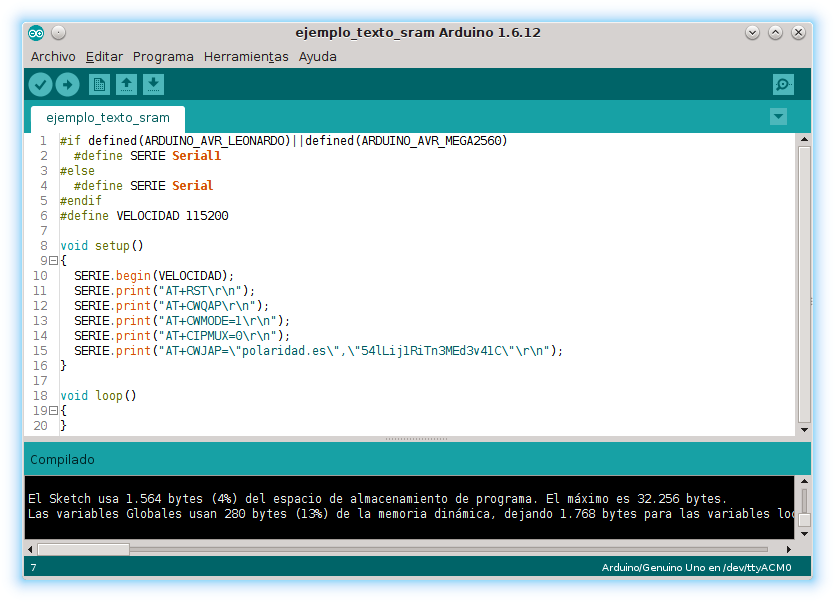
The order of operations does not have to be exactly like this (although the operation is) and each step may require several ESP8266 AT commandsFor example, the configuration listed above would need two: AT+CIPMUX=0 y AT+CWMODE=1.
A data structure to represent operations on the ESP8266
In the previous examples, although in a very basic way, a generic solution to the problem is already suggested: use a data structure that stores the possible responses and the actions that must be taken in each case; send an action, wait for a response, and proceed according to what the response means. Since each complex operation will require several ESP8266 AT commands, the data structure must link an operation with others, subsequent or previous, which must be carried out in each case depending on the response of the ESP8266.
In the previous examples, a message was searched within the response of the ESP8266 and it was interpreted as success or error. In addition to a reception (and analysis) of all the text received, To have a generic minimum, it is advisable to also attend to the completion of the message or, in other words, to the availability of the ESP8266 wifi module to receive new orders. In this way, the change to a state that we could call, for example, "wifi available", could be receiving the name of the access point and receiving the text ERROR or the text OK would mean that the ESP8266 you have finished the response and you can now send the next one AT command to ESP8266.
|
1
2
3
4
5
6
7
8
9
10
11
12
13
14
15
16
17
18
19
20
21
22
23
24
25
26
27
28
29
30
31
32
33
34
35
36
37
38
39
40
41
42
43
44
45
46
47
48
49
50
51
52
53
54
55
56
57
58
59
60
61
62
63
64
65
66
67
68
69
70
71
72
73
74
75
76
77
78
79
80
81
82
83
84
85
86
87
88
89
90
91
92
93
94
95
96
97
98
99
100
101
102
103
104
105
106
107
108
109
110
111
112
113
114
115
116
117
118
119
120
121
122
123
124
125
126
127
128
129
130
131
132
133
|
// inicializar_operaciones.h
// 0 Reiniciar el módulo wifi ESP8266
operacion[REINICIAR_ESP8266]=“AT+RST”;
mensaje[REINICIAR_ESP8266][FALLO]=mensaje_fallo;
mensaje[REINICIAR_ESP8266][ACIERTO]=“ready\r\n”;
mensaje[REINICIAR_ESP8266][LITERAL]=mensaje_vacio;
siguiente_operacion[REINICIAR_ESP8266][FALLO]=REINICIAR_ESP8266;
siguiente_operacion[REINICIAR_ESP8266][ACIERTO]=DESCONECTAR_WIFI;
siguiente_operacion[REINICIAR_ESP8266][LITERAL]=DESCONECTAR_WIFI;
configuracion[REINICIAR_ESP8266]=ESPERAR_RESPUESTA|ACIERTO_TERMINA|FALLO_TERMINA;
timeout[REINICIAR_ESP8266]=10000;
// 1 Desconectar del punto de acceso por defecto (si fuera el caso)
operacion[DESCONECTAR_WIFI]=“AT+CWQAP”;
mensaje[DESCONECTAR_WIFI][FALLO]=mensaje_fallo;
mensaje[DESCONECTAR_WIFI][ACIERTO]=mensaje_acierto;
mensaje[DESCONECTAR_WIFI][LITERAL]=mensaje_vacio;
siguiente_operacion[DESCONECTAR_WIFI][FALLO]=REINICIAR_ESP8266;
siguiente_operacion[DESCONECTAR_WIFI][ACIERTO]=MODO_ESTACION;
siguiente_operacion[DESCONECTAR_WIFI][LITERAL]=MODO_ESTACION;
configuracion[DESCONECTAR_WIFI]=ESPERAR_RESPUESTA|ACIERTO_TERMINA|FALLO_TERMINA;
timeout[DESCONECTAR_WIFI]=2500;
// 2 Establecer el modo de estación (no punto de acceso)
operacion[MODO_ESTACION]=“AT+CWMODE=1”;
mensaje[MODO_ESTACION][FALLO]=mensaje_fallo;
mensaje[MODO_ESTACION][ACIERTO]=mensaje_acierto;
mensaje[MODO_ESTACION][LITERAL]=mensaje_vacio;
siguiente_operacion[MODO_ESTACION][FALLO]=REINICIAR_ESP8266;
siguiente_operacion[MODO_ESTACION][ACIERTO]=MODO_SIMPLE;
siguiente_operacion[MODO_ESTACION][LITERAL]=MODO_SIMPLE;
configuracion[MODO_ESTACION]=ESPERAR_RESPUESTA|ACIERTO_TERMINA|FALLO_TERMINA;
timeout[MODO_ESTACION]=2500;
// 3 Establecer el modo de conexión simple
operacion[MODO_SIMPLE]=“AT+CIPMUX=0”;
mensaje[MODO_SIMPLE][FALLO]=mensaje_fallo;
mensaje[MODO_SIMPLE][ACIERTO]=mensaje_acierto;
mensaje[MODO_SIMPLE][LITERAL]=mensaje_vacio;
siguiente_operacion[MODO_SIMPLE][FALLO]=REINICIAR_ESP8266;
siguiente_operacion[MODO_SIMPLE][ACIERTO]=CONECTAR_WIFI;
siguiente_operacion[MODO_SIMPLE][LITERAL]=CONECTAR_WIFI;
configuracion[MODO_SIMPLE]=ESPERAR_RESPUESTA|ACIERTO_TERMINA|FALLO_TERMINA;
timeout[MODO_SIMPLE]=2500;
// 4 Conectar al punto de acceso
operacion[CONECTAR_WIFI]=“AT+CWJAP=\”polaridad.es\”,\”54lLij1RiTn3MEd3v41C\””;
mensaje[CONECTAR_WIFI][FALLO]=mensaje_fallo;
mensaje[CONECTAR_WIFI][ACIERTO]=mensaje_acierto;
mensaje[CONECTAR_WIFI][LITERAL]=mensaje_vacio;
siguiente_operacion[CONECTAR_WIFI][FALLO]=REINICIAR_ESP8266;
siguiente_operacion[CONECTAR_WIFI][ACIERTO]=VERIFICAR_CONEXION;
siguiente_operacion[CONECTAR_WIFI][LITERAL]=VERIFICAR_CONEXION;
configuracion[CONECTAR_WIFI]=ESPERAR_RESPUESTA|ACIERTO_TERMINA|FALLO_TERMINA;
timeout[CONECTAR_WIFI]=20000;
// 5 Verificar si hay conexión
operacion[VERIFICAR_CONEXION]=“AT+CIPSTATUS”;
mensaje[VERIFICAR_CONEXION][FALLO]=mensaje_fallo;
mensaje[VERIFICAR_CONEXION][ACIERTO]=mensaje_acierto;
mensaje[VERIFICAR_CONEXION][LITERAL]=“STATUS:5”;
siguiente_operacion[VERIFICAR_CONEXION][FALLO]=REINICIAR_ESP8266;
siguiente_operacion[VERIFICAR_CONEXION][ACIERTO]=REINICIAR_ESP8266;
siguiente_operacion[VERIFICAR_CONEXION][LITERAL]=CONECTAR_SERVIDOR;
configuracion[VERIFICAR_CONEXION]=ESPERAR_RESPUESTA|ACIERTO_TERMINA|FALLO_TERMINA;
timeout[VERIFICAR_CONEXION]=5000;
// 6 Conectar al servidor
operacion[CONECTAR_SERVIDOR]=“AT+CIPSTART=\”TCP\”,\”servidoriot.com\”,80″;
mensaje[CONECTAR_SERVIDOR][FALLO]=mensaje_fallo;
mensaje[CONECTAR_SERVIDOR][ACIERTO]=mensaje_acierto;
mensaje[CONECTAR_SERVIDOR][LITERAL]=“CONNECT”;
siguiente_operacion[CONECTAR_SERVIDOR][FALLO]=REINICIAR_ESP8266;
siguiente_operacion[CONECTAR_SERVIDOR][ACIERTO]=INFORMAR_CANTIDAD;
siguiente_operacion[CONECTAR_SERVIDOR][LITERAL]=INFORMAR_CANTIDAD;
configuracion[CONECTAR_SERVIDOR]=ESPERAR_RESPUESTA|ACIERTO_TERMINA|FALLO_TERMINA;
timeout[CONECTAR_SERVIDOR]=15000;
// 7 Avisar de la cantidad de datos que se envían
operacion[INFORMAR_CANTIDAD]=“AT+CIPSEND=”;
mensaje[INFORMAR_CANTIDAD][FALLO]=mensaje_vacio;
mensaje[INFORMAR_CANTIDAD][ACIERTO]=mensaje_acierto;
mensaje[INFORMAR_CANTIDAD][LITERAL]=mensaje_vacio;
siguiente_operacion[INFORMAR_CANTIDAD][FALLO]=REINICIAR_ESP8266;
siguiente_operacion[INFORMAR_CANTIDAD][ACIERTO]=ENVIAR_CANTIDAD;
siguiente_operacion[INFORMAR_CANTIDAD][LITERAL]=ENVIAR_CANTIDAD;
configuracion[INFORMAR_CANTIDAD]=NO_ESPERAR_RESPUESTA;
timeout[INFORMAR_CANTIDAD]=1000;
// 8 Enviar cantidad
//operacion[ENVIAR_CANTIDAD]=”123″; // Definido para cada envío
mensaje[ENVIAR_CANTIDAD][FALLO]=sin_enlace;
mensaje[ENVIAR_CANTIDAD][ACIERTO]=“>”;
mensaje[ENVIAR_CANTIDAD][LITERAL]=mensaje_vacio;
siguiente_operacion[ENVIAR_CANTIDAD][FALLO]=REINICIAR_ESP8266;
siguiente_operacion[ENVIAR_CANTIDAD][ACIERTO]=ENVIAR_PREFIJO_PETICION;
siguiente_operacion[ENVIAR_CANTIDAD][LITERAL]=ENVIAR_PREFIJO_PETICION;
configuracion[ENVIAR_CANTIDAD]=ESPERAR_RESPUESTA|ACIERTO_TERMINA|FALLO_TERMINA;
timeout[ENVIAR_CANTIDAD]=5000;
// 9 Enviar el prefijo de la petición
operacion[ENVIAR_PREFIJO_PETICION]=“GET /frigo03/almacenar_temperatura.php?temperatura=”;
mensaje[ENVIAR_PREFIJO_PETICION][FALLO]=mensaje_vacio;
mensaje[ENVIAR_PREFIJO_PETICION][ACIERTO]=mensaje_vacio;
mensaje[ENVIAR_PREFIJO_PETICION][LITERAL]=mensaje_vacio;
siguiente_operacion[ENVIAR_PREFIJO_PETICION][FALLO]=REINICIAR_ESP8266;
siguiente_operacion[ENVIAR_PREFIJO_PETICION][ACIERTO]=ENVIAR_DATOS;
siguiente_operacion[ENVIAR_PREFIJO_PETICION][LITERAL]=ENVIAR_DATOS;
configuracion[ENVIAR_PREFIJO_PETICION]=NO_ESPERAR_RESPUESTA;
timeout[ENVIAR_PREFIJO_PETICION]=10000;
// 10 Enviar la temperatura
//operacion[ENVIAR_DATOS]=”+000.00″; // Definido para cada envío
mensaje[ENVIAR_DATOS][FALLO]=mensaje_vacio;
mensaje[ENVIAR_DATOS][ACIERTO]=mensaje_vacio;
mensaje[ENVIAR_DATOS][LITERAL]=mensaje_vacio;
siguiente_operacion[ENVIAR_DATOS][FALLO]=REINICIAR_ESP8266;
siguiente_operacion[ENVIAR_DATOS][ACIERTO]=ENVIAR_SUFIJO_PETICION;
siguiente_operacion[ENVIAR_DATOS][LITERAL]=ENVIAR_SUFIJO_PETICION;
configuracion[ENVIAR_DATOS]=NO_ESPERAR_RESPUESTA;
timeout[ENVIAR_DATOS]=5000;
// 11 Enviar el sufijo de la petición
operacion[ENVIAR_SUFIJO_PETICION]=” HTTP/1.1\r\nHost: www.servidoriot.com\r\nUser-Agent: ESP8266\r\nConnection: close\r\n\r\n”;
mensaje[ENVIAR_SUFIJO_PETICION][FALLO]=sin_enlace;
mensaje[ENVIAR_SUFIJO_PETICION][ACIERTO]=“CLOSED\r\n\r\nOK\r\n”;
mensaje[ENVIAR_SUFIJO_PETICION][LITERAL]=mensaje_vacio; // “SEND OK”
siguiente_operacion[ENVIAR_SUFIJO_PETICION][FALLO]=REINICIAR_ESP8266;
siguiente_operacion[ENVIAR_SUFIJO_PETICION][ACIERTO]=VERIFICAR_CONEXION;
siguiente_operacion[ENVIAR_SUFIJO_PETICION][LITERAL]=VERIFICAR_CONEXION;
configuracion[ENVIAR_SUFIJO_PETICION]=ESPERAR_RESPUESTA|ACIERTO_TERMINA|FALLO_TERMINA;
timeout[ENVIAR_SUFIJO_PETICION]=20000;
|
The code above uses a vector (operacion) to store the text of the successive operations that form the complete task. A two-dimensional array is used (mensaje) with the three responses that are analyzed. As explained above, it is necessary to look for the messages that represent the end of the response in addition to the message that represents a correct or incorrect response. Not all operations will have the same number of possible answers; When there are fewer responses, an empty message can be used that consumes the smallest possible number of cycles in its analysis (even so, it is not the most optimal way). Logically, it will be necessary for the minimum number of responses sought (three in the example) to include all the operating possibilities, even if they are not all possible.
When talking about the possible answers, it can already be seen that this example is not very useful for receiving data with an arbitrary format from a ESP8266 wifi module, but the thing is that, in the context of use with microcontrollers it is not usual; The most common thing is to send data collected by the sensors they have connected and/or receive information about what to do with the actuators it controls. Very valuable information, which can be predicted very well.
In the previous data structure, just as it is done to express the possible responses that are analyzed, a two-dimensional matrix is also used to determine the operation that must be performed in each case (siguiente_operacion). Specifically, we have chosen to respond to three types of messages: ① an arbitrary text (LITERAL) to verify if there is a connection to the Wi-Fi access point and the server, ② a text to detect errors in the process (FALLO) and ③ a text indicating that the operation was completed successfully (ACIERTO).
Finally, there are two more vectors to set the maximum wait time before giving up (timeout) and specify (configuracion) if the operation ends without waiting for a response (ESPERAR_RESPUESTA) and messages indicating the end of the communication. This last vector, to illustrate an example of how memory could be saved, works with the bits of a configuration byte to indicate the different states.
The first ESP8266 AT commands of the data structure always expect a response, which can be the success or error message. When an error occurs, the module is restarted and it starts again and if the message indicates that the operation is correct, it moves on to the next one.
When you have connected to the server, the pattern changes. In this case it is necessary to ① send the length of the data packet to be transmitted and ② compose the request HTTP with a fixed text plus the value (of the temperature) that is sent to be stored on the server. The preparation of this data is carried out in each shipment and it is necessary to divide it into two (notify the length) or three (send the request HTTP) the ESP8266 AT order. Only the last of the parts into which the operation is divided will wait for a response.
In this case it will work without problems (maybe warning that the module is busy) but when the length of the data is greater it will be necessary to divide the data blocks into smaller pieces and it may even be necessary to implement a wait, as is done with the temperature reading, to give the module time to send the data without filling its buffer.
|
1
2
3
4
5
6
7
8
9
10
11
12
13
14
15
16
17
18
19
20
21
22
23
24
25
26
27
28
29
30
31
32
33
|
#if defined(ARDUINO_AVR_LEONARDO)||defined(ARDUINO_AVR_MEGA2560) /* ¿Es una placa Arduino Mega 2560 o Arduino Leonardo? */
#define SERIE Serial1 /* Si es una placa Arduino Mega 2560 o Arduino Leonardo usar Serial1 */
#else /* En este proyecto solamente uso Placas Leonardo, Mega 2560 y Uno, así que tiene que ser un Arduino Uno si llega hasta aquí */
#define SERIE Serial /* Si es una placa Arduino Uno usar Serial */
#endif
#define VELOCIDAD 115200 // Velocidad (en baudios) al que está configurado el módulo wifi ESP8266 (Cuidado con la placa utilizada, no todas o siempre son capaces de trabajar a una velocidad tan alta)
#define REINICIAR_ESP8266 0 // Índice del vector de operaciones que representa la orden de reinicio del módulo wifi ESP8266
#define DESCONECTAR_WIFI 1
#define MODO_ESTACION 2
#define MODO_SIMPLE 3
#define CONECTAR_WIFI 4
#define VERIFICAR_CONEXION 5
#define CONECTAR_SERVIDOR 6
#define INFORMAR_CANTIDAD 7
#define ENVIAR_CANTIDAD 8
#define ENVIAR_PREFIJO_PETICION 9
#define ENVIAR_DATOS 10
#define ENVIAR_SUFIJO_PETICION 11
#define CANTIDAD_OPERACIONES 12 // Cantidad de operaciones que forma el cuerpo de la aplicación
#define FALLO 0 // Índice del vector de respuestas que representa el mensaje de error
#define FALLO_TERMINA 0B00000001 // 1<<FALLO
#define ACIERTO 1
#define ACIERTO_TERMINA 0B00000010 // 1<<ACIERTO
#define LITERAL 2
#define LITERAL_TERMINA 0B00000100 // 1<<LITERAL
#define CANTIDAD_RESPUESTAS 3 // Cantidad de posibles respuestas que se buscan en el texto recibido desde el ESP8266
#define ESPERAR_RESPUESTA 0B00001000 // 1<<CANTIDAD_RESPUESTAS
#define NO_ESPERAR_RESPUESTA 0B00000000
#define ENVIAR_OPERACION esperando_respuesta=true;SERIE.print(operacion[operacion_actual]);if(configuracion[operacion_actual]&ESPERAR_RESPUESTA){SERIE.print(“\r\n”);}for(unsigned char numero_respuesta=0;numero_respuesta<CANTIDAD_RESPUESTAS;numero_respuesta++){numero_caracter[numero_respuesta]=0;}cronometro_esp8266=millis();
|
Together with other macros that have already been explained before, the example code above shows how the different states are defined with which to specify whether to wait for a response and, if applicable, what message indicates that it has finished.
As at different points in the code an operation will be sent (when it is time to send the average temperature, if the waiting time of an operation is exceeded, when the current operation is successfully completed...) but how to do it is established globally, it has been defined a macro ENVIAR_OPERACION which groups the steps involved in shipping.
|
1
2
3
4
5
6
7
8
9
10
11
12
|
// La macro ENVIAR_OPERACION corresponde con las operaciones:
esperando_respuesta=true;
SERIE.print(operacion[operacion_actual]);
if(configuracion[operacion_actual]&ESPERAR_RESPUESTA)
{
SERIE.print(“\r\n”);
}
for(unsigned char numero_respuesta=0;numero_respuesta<CANTIDAD_RESPUESTAS;numero_respuesta++)
{
numero_caracter[numero_respuesta]=0;
}
cronometro_esp8266=millis();
|
The following is the code of the main program of the example. The most external task is the one in charge of sampling the temperature to calculate the average and, every certain period of time, it is sent to the server using the ESP8266 wifi module. Once each operation is sent, the response is analyzed to determine which is next or if the task of sending information has been completed.
|
1
2
3
4
5
6
7
8
9
10
11
12
13
14
15
16
17
18
19
20
21
22
23
24
25
26
27
28
29
30
31
32
33
34
35
36
37
38
39
40
41
42
43
44
45
46
47
48
49
50
51
52
53
54
55
56
57
58
59
60
61
62
63
64
65
66
67
68
69
70
71
72
73
74
75
76
77
78
79
80
81
82
83
84
85
86
87
88
89
90
91
92
93
94
95
96
97
98
99
100
101
102
103
104
105
106
107
108
109
110
111
112
113
114
115
116
117
118
119
120
|
#include “ESP8266_operacion_compleja_varias_ordenes_AT.h”
#define PIN_TEMPERATURA A0 // Pin analógico al que se conecta la salida del sensor de temperatura LM35
#define INTERVALO_LECTURA_TEMPERATURA 30000 // Leer la temperatura cada 30 segundos (30*1000)
#define INTERVALO_GRABACION_TEMPERATURA 300000 // Grabar la media de la temperatura cada 5 minutos (5*60*1000)
unsigned long muestras=0; // Número de veces que se ha medido la temperatura (para calcular la media)
float temperatura; // de -55.0 °C a +150 °C | de 0 V a 2.050 V | de -550 mV a +1500 mV | analogRead*5.0/1023.0*100-55.0 analogRead/2.46-55.0
float media_temperaturas=0.0;
unsigned long cronometro_lectura_temperatura;
unsigned long cronometro_grabacion_temperatura;
char *mensaje_fallo=“ERROR\r\n”;
char *mensaje_acierto=“OK\r\n”;
char *sin_enlace=“link is not\r\n”;
char *mensaje_vacio=“\f”;
char *operacion[CANTIDAD_OPERACIONES]; // Matriz de punteros a constantes de caracteres con las operaciones que se envían al ESP8266 (no solo órdenes AT, aunque seguro que algunas son órdenes AT)
char *mensaje[CANTIDAD_OPERACIONES][CANTIDAD_RESPUESTAS]; // Mensajes de respuesta
unsigned char siguiente_operacion[CANTIDAD_OPERACIONES][CANTIDAD_RESPUESTAS];
unsigned char configuracion[CANTIDAD_OPERACIONES];
unsigned int timeout[CANTIDAD_OPERACIONES];
unsigned char numero_caracter[CANTIDAD_RESPUESTAS];
unsigned int longitud_peticion;
char texto_longitud_peticion[4]; // 3 caracteres para almacenar la longitud de la petición en formato texto
char valor_enviado[9]; // signo + 4 enteros + punto + 2 decimales + \0 = 9
unsigned long cronometro_esp8266;
unsigned char operacion_actual; // Número de operación que se está procesando
unsigned char proxima_operacion; // Siguiente operación que se procesará cuando termine la actual
char lectura_serie;
boolean grabando_datos=false;
boolean esperando_respuesta;
void setup()
{
#include “inicializar_operaciones.h”
longitud_peticion=strlen(operacion[ENVIAR_PREFIJO_PETICION])+strlen(operacion[ENVIAR_SUFIJO_PETICION]);
SERIE.begin(VELOCIDAD); // Configurar el puerto serie de Arduino a la velocidad del ESP8266
//delay(8000); // En fase de pruebas se puede introducir un tiempo de espera para conectar una consola/sniffer
cronometro_lectura_temperatura=millis();
cronometro_grabacion_temperatura=millis();
}
void loop()
{
if((unsigned long)(millis()–cronometro_lectura_temperatura)>INTERVALO_LECTURA_TEMPERATURA)
{
cronometro_lectura_temperatura=millis();
temperatura=analogRead(PIN_TEMPERATURA)/2.46–55.0;
muestras++;
media_temperaturas=(float)temperatura/(float)muestras+media_temperaturas*(float)(muestras–1)/(float)(muestras);
}
if(grabando_datos)
{
if((unsigned long)(millis()–cronometro_esp8266)>timeout[operacion_actual]) // Si se ha superado el tiempo de espera máximo
{
operacion_actual=siguiente_operacion[operacion_actual][FALLO]; // Pasar a la operación correspondiente al error
ENVIAR_OPERACION
}
else // Si no se ha superado el tiempo de espera máximo
{
if(configuracion[operacion_actual]&ESPERAR_RESPUESTA) // Si la siguiente operación depende de la respuesta a la actual desde el ESP8266 hay que leer la información que llegue desde el puerto serie
{
while(SERIE.available())
{
lectura_serie=SERIE.read();
for(unsigned char numero_respuesta=0;numero_respuesta<CANTIDAD_RESPUESTAS;numero_respuesta++) // Comparar la letra cargada desde el puerto serie con la correspondiente de los mensajes disponibles
{
if(lectura_serie==mensaje[operacion_actual][numero_respuesta][numero_caracter[numero_respuesta]]) // Si el dato que ha llegado es igual al que correspondería del mensaje buscado…
{
numero_caracter[numero_respuesta]++; // Como el carácter coincide, se puede comparar con el siguiente lo próximo que llegue por el puerto serie
if(mensaje[operacion_actual][numero_respuesta][numero_caracter[numero_respuesta]]==0) // Si el carácter que toca es \0 es que se ha terminado de analizar el mensaje
{
if(esperando_respuesta) // Todavía no se ha encontrado un mensaje que determine la siguiente operación
{
proxima_operacion=siguiente_operacion[operacion_actual][numero_respuesta]; // La próxima operación que habrá que procesar será la que indique el mensaje encontrado para la operación actual
esperando_respuesta=false; // Ya se ha encontrado un mensaje que determina la siguiente operación
}
if(configuracion[operacion_actual]&(1<<numero_respuesta)) // Si el mensaje encontrado es uno de los que terminan la operación…
{
if(operacion_actual+1==CANTIDAD_OPERACIONES) // Se ha completado la última operación de la tarea compleja
{
grabando_datos=false; // Se ha terminado la tarea compleja (grabar datos en el servidor)
}
else // No es la última operación de la tarea compleja, hay que seguir realizando otras operaciones
{
operacion_actual=proxima_operacion; // Ejecutar la siguiente operación
ENVIAR_OPERACION
}
}
}
}
else // Si la letra recibida no es igual que la correspondiente del mensaje
{
numero_caracter[numero_respuesta]=0; // Empezar a comparar desde la primera letra del mensaje
}
}
}
}
else // Si no hay que esperar datos desde el puerto serie
{
operacion_actual=siguiente_operacion[operacion_actual][ACIERTO];
ENVIAR_OPERACION
}
}
}
else
{
if((unsigned long)(millis()–cronometro_grabacion_temperatura)>INTERVALO_GRABACION_TEMPERATURA)
{
cronometro_grabacion_temperatura=millis();
dtostrf(media_temperaturas,4,2,valor_enviado); // snprintf(valor_enviado,9,”%+3.2f”,media_temperaturas); // printf y derivadas no funcionan en AVR
snprintf(texto_longitud_peticion,4,“%d”,longitud_peticion+strlen(valor_enviado));
grabando_datos=true;
operacion_actual=VERIFICAR_CONEXION;
operacion[ENVIAR_DATOS]=valor_enviado;
operacion[ENVIAR_CANTIDAD]=texto_longitud_peticion;
ENVIAR_OPERACION
}
}
}
|
Logically, several optimization actions can be carried out on the previous code but, as this is an example to understand how the ESP8266 In a generic way, it is only worth focusing on some aspects, the first being the data structure. It seems that the logical thing is use a programming language data structure (struct) to represent the information being processed: The ESP8266 AT commands and the messages that are analyzed.
Use a structure (struct) to store the data instead of the example arrays (based on them) is trivial and, although it may result in more elegant code, it does not imply any improvement in the result. The true alternative posed by the use of struct is to implement, as explained below, variable lengths in structures that contain “inner” data that are referred to by them. In this way, for example, it would not be necessary for an operation to have a fixed number of responses to analyze.
This approach suggests that it is the best way to implement the solution but the drawback is that it would be necessary use dynamic memory allocation, a risky practice working with a microcontroller which requires careful measurement of how much memory will be used at runtime, since the compiler will hardly be able to warn us about this and there is a certain possibility of exhausting the memory (or the stack) with fatal consequences for the execution of the program.
In the line of optimizing the code, it is interesting to remember that, in a program of this type, which uses a large amount of text, can save memory space SRAM storing text strings in program memory (flash) with the macro F(). In the following screenshots you can see the different program and dynamic memory distribution with normal use of text and using the macro F().

With respect to the actions that are executed according to the information that arrives from the ESP8266 wifi module, as an alternative to checking the message from the code and performing one or the other according to what is received, can be stored in this data structure pointers to functions that perform each task instead of status indicators (flags) that warn of a certain state that the application is responsible for managing, for example, within the main loop.
The following is an example of structures to store the data of the requests to the ESP8266 (the data type operacion_esp8266) and their responses (the data type respuesta_esp8266).
|
1
2
3
4
5
6
7
8
9
10
11
12
13
14
15
16
17
18
19
20
21
22
23
24
|
typedef struct estructura_operacion_esp8266 operacion_esp8266; // Se define el tipo de datos operacion_esp8266 que corresponde con la estructura (struct) llamada estructura_operacion_esp8266 que se define más adelante
typedef struct estructura_respuesta_esp8266 respuesta_esp8266; // Se define el tipo de datos respuesta_esp8266 que corresponde con la estructura (struct) llamada struct estructura_respuesta_esp8266 que se define más adelante
struct estructura_operacion_esp8266
{
char *peticion; // Datos que se envían al ESP8266 para iniciar una operación (como una orden AT, pero también algo como la petición a un servidor…)
unsigned char cantidad_respuestas; // Número de posibles respuestas del ESP8266 que se van a analizar, que puede ser variable en cada petición (no solo OK y ERROR)
unsigned char timeout; // Tiempo (segundos) que se espera la respuesta del ESP8266 antes de desistir
respuesta_esp8266 *respuesta; // Respuestas (estructura) que se esperan de esta operación
};
struct estructura_respuesta_esp8266
{
char *mensaje; // Mensaje que se espera recibir desde el ESP8266
unsigned char posicion_mensaje; // Posición (letra) que se está comparando con la recibida desde el ESP8266
//boolean estado; // El estado se representa por un valor booleano (por ejemplo ¿se ha encontrado ya esta respuesta? para no seguir buscándola)
//unsigned char *estado; // El estado se representa con un texto (de longitud variable)
unsigned char estado; // El estado se establece con 8 banderas, una por bit
operacion_esp8266 *operacion; // Puntero a operación que se ejecutará si se encuentra esta respuesta en el mensaje devuelto por el ESP8266
};
operacion_esp8266 comprobar_conexion;
respuesta_esp8266 respuesta_OK;
respuesta_esp8266 respuesta_ERROR;
|
As the structure that represents the operation (the data that is sent to the ESP8266 wifi module) refers to the structure with which the responses are defined, and the structure of the responses to the structure of the operations, it is necessary to declare both first, by defining the new data type, and then defining its contents.
The previous example considers that the program that includes it has chosen to use a status indicator, which must correspond to a variable accessible from the code that is responsible for performing one or other operations as indicated by said value. If in the response of ESP8266 When a certain text is analyzed, the state takes the value that indicates the structure of the corresponding response.
As said before, another alternative, either to replace or complement a status indicator, would be store a function in the reference structure (a pointer) that would be called upon encountering certain text in the response from the ESP8266 wifi module.
|
1
2
3
4
5
6
7
8
9
10
11
12
13
14
15
16
17
18
19
20
21
22
23
24
25
|
typedef struct estructura_operacion_esp8266 operacion_esp8266; // Se define el tipo de datos operacion_esp8266 que corresponde con la estructura (struct) llamada estructura_operacion_esp8266 que se define más adelante
typedef struct estructura_respuesta_esp8266 respuesta_esp8266; // Se define el tipo de datos respuesta_esp8266 que corresponde con la estructura (struct) llamada struct estructura_respuesta_esp8266 que se define más adelante
struct estructura_operacion_esp8266
{
char *peticion; // Datos que se envían al ESP8266 para iniciar una operación (como una orden AT, pero también algo como la petición a un servidor…)
unsigned char cantidad_respuestas; // Número de posibles respuestas del ESP8266 que se van a analizar, que puede ser variable en cada petición (no solo OK y ERROR)
unsigned char timeout; // Tiempo (segundos) que se espera la respuesta del ESP8266 antes de desistir
respuesta_esp8266 *respuesta; // Respuestas (estructura) que se esperan de esta operación
};
struct estructura_respuesta_esp8266
{
char *mensaje; // Mensaje que se espera recibir desde el ESP8266
unsigned char posicion_mensaje; // Posición (letra) que se está comparando con la recibida desde el ESP8266
//boolean estado; // El estado se representa por un valor booleano (por ejemplo ¿se ha encontrado ya esta respuesta? para no seguir buscándola)
//unsigned char *estado; // El estado se representa con un texto (de longitud variable)
unsigned char estado; // El estado se establece con 8 banderas, una por bit
float (*accion)(unsigned char,unsigned char); // Puntero a la función que se llama si se encuentra la respuesta
operacion_esp8266 *operacion; // Puntero a operación que se ejecutará si se encuentra esta respuesta en el mensaje devuelto por el ESP8266
};
operacion_esp8266 comprobar_conexion;
respuesta_esp8266 respuesta_OK;
respuesta_esp8266 respuesta_ERROR;
|
In the previous example, it has been added to the data structure that is used to process the response from the ESP8266 wifi module a pointer to a (supposed) function that returns a data of type float (could be the weighted value of an analog reading) and to which two bytes are provided as arguments (two unsigned char which could be the pin from which the analog input is read and the one that activates the ENABLE of a hypothetical integrated).
In development for MCU, contrary to what occurs in the development style for larger systems, it is not so uncommon to use global variables when defining the (global) behavior of the application that controls an assembly, so it will not be especially rare to find this type of definitions as functions without parameters and that do not return values, something like void (*accion)();
If you work with this way of representing the data, using struct of variable length data, it will be necessary to dynamically allocate memory with malloc() (o new(), if objects are used), which will use the amount of memory allocated as a parameter and return a pointer to the beginning of the memory area that is reserved. With sizeof() On the type that are stored, multiplied by the number of elements used, you can get the amount of memory that is needed. An example with and without using it can be seen in the screenshots below. malloc(); Be careful with the memory used by the program in the first case, you need to load the library that contains this function.


If the operations on the ESP8266 wifi module will vary throughout the execution of the program, it will be necessary to free the memory that is not used with free() (o delete(), in the case of being objects). Although it is reasonable to expect that the compiler (GCC) will optimize the program to avoid memory partitioning, surely the performance will not be as optimal as working with statically allocated memory.
|
1
2
3
4
5
6
7
8
9
10
11
12
13
14
15
16
17
18
19
20
21
22
23
24
25
26
27
28
29
30
31
32
33
34
35
36
37
38
39
40
41
42
43
44
45
46
47
48
49
50
51
52
53
54
55
56
57
58
59
60
61
62
63
64
65
66
67
68
69
70
71
72
73
74
75
76
77
78
79
80
81
82
83
84
85
86
87
88
89
90
91
92
93
94
95
96
97
98
99
100
101
102
103
104
105
106
107
108
109
110
111
112
113
114
115
116
117
118
119
120
121
122
123
124
125
126
127
128
129
130
131
132
133
134
135
136
137
138
139
140
141
142
|
error_operacion.mensaje=“ERROR\r\n”;
error_operacion.termina_operacion=true;
error_operacion.operacion=&reiniciar_esp8266;
error_enlace.mensaje=“link is not\r\n”;
error_enlace.termina_operacion=true;
error_enlace.operacion=&reiniciar_esp8266;
reiniciar_esp8266_correcto.mensaje=“ready\r\n”;
reiniciar_esp8266_correcto.termina_operacion=true;
reiniciar_esp8266_correcto.operacion=&desconectar_wifi;
desconectar_wifi_correcto.mensaje=mensaje_acierto;
desconectar_wifi_correcto.termina_operacion=true;
desconectar_wifi_correcto.operacion=&establecer_modo_estacion;
establecer_modo_estacion_correcto.mensaje=mensaje_acierto;
establecer_modo_estacion_correcto.termina_operacion=true;
establecer_modo_estacion_correcto.operacion=&establecer_modo_simple;
establecer_modo_simple_correcto.mensaje=mensaje_acierto;
establecer_modo_simple_correcto.termina_operacion=true;
establecer_modo_simple_correcto.operacion=&conectar_wifi;
conectar_wifi_correcto.mensaje=mensaje_acierto;
conectar_wifi_correcto.termina_operacion=true;
conectar_wifi_correcto.operacion=&verificar_conexion;
verificar_conexion_correcto.mensaje=“STATUS:5”;
verificar_conexion_correcto.termina_operacion=false;
verificar_conexion_correcto.operacion=&conectar_servidor;
verificar_conexion_terminado.mensaje=mensaje_acierto;
verificar_conexion_terminado.termina_operacion=true;
verificar_conexion_terminado.operacion=&reiniciar_esp8266;
conectar_servidor_correcto.mensaje=“CONNECT”;
conectar_servidor_correcto.termina_operacion=false;
conectar_servidor_correcto.operacion=&informar_cantidad;
conectar_servidor_terminado.mensaje=mensaje_acierto;
conectar_servidor_terminado.termina_operacion=true;
conectar_servidor_terminado.operacion=&reiniciar_esp8266;
informar_cantidad_correcto.mensaje=mensaje_acierto;
informar_cantidad_correcto.termina_operacion=true;
informar_cantidad_correcto.operacion=&enviar_cantidad;
enviar_cantidad_correcto.mensaje=“>”;
enviar_cantidad_correcto.termina_operacion=true;
enviar_cantidad_correcto.operacion=&enviar_prefijo;
enviar_prefijo_correcto.operacion=&enviar_datos;
enviar_datos_correcto.operacion=&enviar_sufijo;
enviar_sufijo_correcto.mensaje=“CLOSED\r\n\r\nOK\r\n”;
enviar_sufijo_correcto.termina_operacion=true;
enviar_sufijo_correcto.operacion=&verificar_conexion;
reiniciar_esp8266.peticion=“AT+RST”;
reiniciar_esp8266.timeout=15000;
reiniciar_esp8266.cantidad_respuestas=2;
reiniciar_esp8266.respuesta=malloc(sizeof(respuesta_esp8266*)*reiniciar_esp8266.cantidad_respuestas);
reiniciar_esp8266.respuesta[FALLO]=&error_operacion;
reiniciar_esp8266.respuesta[ACIERTO]=&reiniciar_esp8266_correcto;
desconectar_wifi.peticion=“AT+CWQAP”;
desconectar_wifi.timeout=2500;
desconectar_wifi.cantidad_respuestas=2;
desconectar_wifi.respuesta=malloc(sizeof(respuesta_esp8266*)*desconectar_wifi.cantidad_respuestas);
desconectar_wifi.respuesta[FALLO]=&error_operacion;
desconectar_wifi.respuesta[ACIERTO]=&desconectar_wifi_correcto;
establecer_modo_estacion.peticion=“AT+CWMODE=1”;
establecer_modo_estacion.timeout=2500;
establecer_modo_estacion.cantidad_respuestas=2;
establecer_modo_estacion.respuesta=malloc(sizeof(respuesta_esp8266*)*establecer_modo_estacion.cantidad_respuestas);
establecer_modo_estacion.respuesta[FALLO]=&error_operacion;
establecer_modo_estacion.respuesta[ACIERTO]=&establecer_modo_estacion_correcto;
establecer_modo_simple.peticion=“AT+CIPMUX=0”;
establecer_modo_simple.timeout=2500;
establecer_modo_simple.cantidad_respuestas=2;
establecer_modo_simple.respuesta=malloc(sizeof(respuesta_esp8266*)*establecer_modo_simple.cantidad_respuestas);
establecer_modo_simple.respuesta[FALLO]=&error_operacion;
establecer_modo_simple.respuesta[ACIERTO]=&establecer_modo_simple_correcto;
conectar_wifi.peticion=“AT+CWJAP=\”polaridad.es\”,\”54lLij1RiTn3MEd3v41C\””;;
conectar_wifi.timeout=20000;
conectar_wifi.cantidad_respuestas=2;
conectar_wifi.respuesta=malloc(sizeof(respuesta_esp8266*)*conectar_wifi.cantidad_respuestas);
conectar_wifi.respuesta[FALLO]=&error_operacion;
conectar_wifi.respuesta[ACIERTO]=&conectar_wifi_correcto;
verificar_conexion.peticion=“AT+CIPSTATUS”;
verificar_conexion.timeout=5000;
verificar_conexion.cantidad_respuestas=3;
verificar_conexion.respuesta=malloc(sizeof(respuesta_esp8266*)*verificar_conexion.cantidad_respuestas);
verificar_conexion.respuesta[FALLO]=&error_operacion;
verificar_conexion.respuesta[ACIERTO]=&verificar_conexion_correcto;
verificar_conexion.respuesta[OTRO_MENSAJE]=&verificar_conexion_terminado;
conectar_servidor.peticion=“AT+CIPSTART=\”TCP\”,\”servidoriot.com\”,80″;
conectar_servidor.timeout=15000;
conectar_servidor.cantidad_respuestas=3;
conectar_servidor.respuesta=malloc(sizeof(respuesta_esp8266*)*conectar_servidor.cantidad_respuestas);
conectar_servidor.respuesta[FALLO]=&error_operacion;
conectar_servidor.respuesta[ACIERTO]=&conectar_servidor_correcto;
conectar_servidor.respuesta[OTRO_MENSAJE]=&conectar_servidor_terminado; // OK, no significa que haya conexión pero sí termina la operación
informar_cantidad.peticion=“AT+CIPSEND=”;
informar_cantidad.timeout=1000;
informar_cantidad.cantidad_respuestas=1;
informar_cantidad.respuesta=malloc(sizeof(respuesta_esp8266*)*informar_cantidad.cantidad_respuestas);
informar_cantidad.respuesta[0]=&informar_cantidad_correcto;
//enviar_cantidad.peticion=””; // Se asigna cuando se conoce el valor que se va a enviar y se puede calcular la longitud que ocupa (número de caracteres)
enviar_cantidad.timeout=5000;
enviar_cantidad.cantidad_respuestas=2;
enviar_cantidad.respuesta=malloc(sizeof(respuesta_esp8266*)*enviar_cantidad.cantidad_respuestas);
enviar_cantidad.respuesta[FALLO]=&error_enlace;
enviar_cantidad.respuesta[ACIERTO]=&enviar_cantidad_correcto;
enviar_prefijo.peticion=“GET /frigo03/almacenar_temperatura.php?temperatura=”;
enviar_prefijo.timeout=10000;
enviar_prefijo.cantidad_respuestas=1;
enviar_prefijo.respuesta=malloc(sizeof(respuesta_esp8266*)*enviar_prefijo.cantidad_respuestas);
enviar_prefijo.respuesta[0]=&enviar_prefijo_correcto;
//enviar_datos.peticion=””; // Se asigna en cuando se conoce el valor que se va a enviar
enviar_datos.timeout=5000;
enviar_datos.cantidad_respuestas=1;
enviar_datos.respuesta=malloc(sizeof(respuesta_esp8266*)*enviar_datos.cantidad_respuestas);
enviar_datos.respuesta[0]=&enviar_datos_correcto;
enviar_sufijo.peticion=” HTTP/1.1\r\nHost: www.servidoriot.com\r\nUser-Agent: ESP8266\r\nConnection: close\r\n\r\n”;
enviar_sufijo.timeout=20000;
enviar_sufijo.cantidad_respuestas=2;
enviar_sufijo.respuesta=malloc(sizeof(respuesta_esp8266*)*enviar_sufijo.cantidad_respuestas);
enviar_sufijo.respuesta[FALLO]=&error_enlace;
enviar_sufijo.respuesta[ACIERTO]=&enviar_sufijo_correcto;
|
|
1
2
3
4
5
6
7
8
9
10
11
12
13
14
15
16
17
18
19
20
21
22
23
24
25
26
27
28
29
30
31
32
33
34
35
36
37
38
39
40
41
42
43
44
45
46
47
48
49
50
51
52
53
54
55
56
57
58
59
60
61
62
63
64
65
66
67
68
69
70
71
72
73
74
75
76
77
78
79
80
81
82
83
84
85
86
87
88
89
90
91
92
93
94
95
96
97
98
99
100
101
102
103
104
105
106
107
108
109
110
111
112
113
114
115
116
117
118
119
120
121
122
123
124
125
126
127
128
129
130
131
132
133
134
135
136
137
138
139
140
141
142
143
144
145
146
147
148
149
150
151
152
153
154
155
156
157
158
159
160
161
162
163
164
165
166
167
168
169
170
171
172
173
174
175
176
177
178
179
180
181
|
#if defined(ARDUINO_AVR_LEONARDO)||defined(ARDUINO_AVR_MEGA2560) /* ¿Es una placa Arduino Mega 2560 o Arduino Leonardo? */
#define SERIE Serial1 /* Si es una placa Arduino Mega 2560 o Arduino Leonardo usar Serial1 */
#else /* En este proyecto solamente uso Placas Leonardo, Mega 2560 y Uno, así que tiene que ser un Arduino Uno si llega hasta aquí */
#define SERIE Serial /* Si es una placa Arduino Uno usar Serial */
#endif
#define VELOCIDAD 115200 // Velocidad (en baudios) al que está configurado el módulo wifi ESP8266 (Cuidado con la placa utilizada, no todas o siempre son capaces de trabajar a una velocidad tan alta)
#define FALLO 0 // Índice del vector de respuestas que representa el mensaje de error
#define FALLO_TERMINA 0B00000001 // 1<<FALLO
#define ACIERTO 1
#define ACIERTO_TERMINA 0B00000010 // 1<<ACIERTO
#define OTRO_MENSAJE 2
#define OTRO_MENSAJE_TERMINA 0B00000100 // 1<<OTRO_MENSAJE
#define CANTIDAD_RESPUESTAS 3 // Cantidad de posibles respuestas que se buscan en el texto recibido desde el ESP8266
#define ESPERAR_RESPUESTA 0B00001000 // 1<<CANTIDAD_RESPUESTAS
#define NO_ESPERAR_RESPUESTA 0B00000000
#define ENVIAR_OPERACION esperando_respuesta=true;SERIE.print((*operacion_actual).peticion);if((*operacion_actual).cantidad_respuestas>1){SERIE.print(“\r\n”);for(unsigned char numero_respuesta=0;numero_respuesta<(*operacion_actual).cantidad_respuestas;numero_respuesta++){numero_caracter[numero_respuesta]=0;}}cronometro_esp8266=millis();
#define PIN_TEMPERATURA A0 // Pin analógico al que se conecta la salida del sensor de temperatura LM35
#define INTERVALO_LECTURA_TEMPERATURA 30000 // Leer la temperatura cada 30 segundos (30*1000)
#define INTERVALO_GRABACION_TEMPERATURA 300000 // Grabar la media de la temperatura cada 5 minutos (5*60*1000)
unsigned long muestras=0; // Número de veces que se ha medido la temperatura (para calcular la media)
float temperatura; // de -55.0 °C a +150 °C | de 0 V a 2.050 V | de -550 mV a +1500 mV | analogRead*5.0/1023.0*100-55.0 analogRead/2.46-55.0
float media_temperaturas=0.0;
unsigned long cronometro_lectura_temperatura;
unsigned long cronometro_grabacion_temperatura;
char *mensaje_acierto=“OK\r\n”;
typedef struct estructura_operacion_esp8266 operacion_esp8266; // Se define el tipo de datos operacion_esp8266 que corresponde con la estructura (struct) llamada estructura_operacion_esp8266 que se define más adelante
typedef struct estructura_respuesta_esp8266 respuesta_esp8266; // Se define el tipo de datos respuesta_esp8266 que corresponde con la estructura (struct) llamada struct estructura_respuesta_esp8266 que se define más adelante
struct estructura_operacion_esp8266
{
char *peticion; // Datos que se envían al ESP8266 para iniciar una operación (como una orden AT, pero también algo como la petición a un servidor…)
unsigned int timeout; // Tiempo (segundos) que se espera la respuesta del ESP8266 antes de desistir
bool espera_respuesta; // Si no espera respuesta en cuanto se termine de enviar la orden se puede pasar a la siguiente
unsigned char cantidad_respuestas; // Número de posibles respuestas del ESP8266 que se van a analizar, que puede ser variable en cada petición (no solo OK y ERROR)
respuesta_esp8266 **respuesta; // Respuestas (estructura) que se esperan de esta operación
};
struct estructura_respuesta_esp8266
{
char *mensaje; // Mensaje que se espera recibir desde el ESP8266
bool termina_operacion; // Cuando se termina de leer el mensaje ha terminado la operación
operacion_esp8266 *operacion; // Puntero a operación que se ejecutará si se encuentra esta respuesta en el mensaje devuelto por el ESP8266
};
operacion_esp8266 *operacion_actual; // Operación sobre el ESP8266 que se está ejecutando actualmente
operacion_esp8266 *proxima_operacion; // Siguiente operación que se procesará cuando termine la actual
unsigned int longitud_peticion; // Número de caracteres que ocupa la petición HTTP
char texto_longitud_peticion[4]; // 3 caracteres para almacenar la longitud de la petición en formato texto
char valor_enviado[9]; // signo + 4 enteros + punto + 2 decimales + \0 = 9
unsigned long cronometro_esp8266; // Cronómetro para controlar el tiempo máximo de respuesta del ESP8266 antes de desistir
char lectura_serie; // buffer con el carácter leído desde el ESP8266
boolean grabando_datos=false; // Verdadero cuando han terminado todas las operaciones necesarias para grabar los datos
boolean esperando_respuesta; // Verdadero si aún no se ha encontrado una de los mensajes que indica que ha terminado la respuesta
unsigned char numero_caracter[CANTIDAD_RESPUESTAS]; // Número de orden de la letra del mensaje-respuesta que se está almacenando (una matriz de, como máximo, el mayor número de respuestas posible)
operacion_esp8266 reiniciar_esp8266; // Reiniciar el módulo wifi ESP8266
operacion_esp8266 desconectar_wifi; // Desconectar del punto de acceso por defecto (si fuera el caso)
operacion_esp8266 establecer_modo_estacion; // Establecer el modo de estación (no punto de acceso)
operacion_esp8266 establecer_modo_simple; // Establecer el modo de conexión simple
operacion_esp8266 conectar_wifi; // Conectar al punto de acceso
operacion_esp8266 verificar_conexion; // Verificar si hay conexión
operacion_esp8266 conectar_servidor; // Conectar al servidor
operacion_esp8266 informar_cantidad; // Avisar de la cantidad de datos que se envían
operacion_esp8266 enviar_cantidad; // Enviar cantidad
operacion_esp8266 enviar_prefijo; // Enviar el prefijo de la petición
operacion_esp8266 enviar_datos; // Enviar la temperatura
operacion_esp8266 enviar_sufijo; // Enviar el sufijo de la petición
respuesta_esp8266 error_operacion; // Todas las respuestas “ERROR” reinician el módulo wifi ESP8266
respuesta_esp8266 error_enlace; // Las respuestas “link is not” también reinician el módulo wifi ESP8266
respuesta_esp8266 reiniciar_esp8266_correcto;
respuesta_esp8266 desconectar_wifi_correcto;
respuesta_esp8266 establecer_modo_estacion_correcto;
respuesta_esp8266 establecer_modo_simple_correcto;
respuesta_esp8266 conectar_wifi_correcto;
respuesta_esp8266 verificar_conexion_correcto;
respuesta_esp8266 verificar_conexion_terminado;
respuesta_esp8266 conectar_servidor_correcto;
respuesta_esp8266 conectar_servidor_terminado;
respuesta_esp8266 informar_cantidad_correcto;
respuesta_esp8266 enviar_cantidad_correcto;
respuesta_esp8266 enviar_prefijo_correcto;
respuesta_esp8266 enviar_datos_correcto;
respuesta_esp8266 enviar_sufijo_correcto;
void setup()
{
#include “inicializar_operaciones.h”
longitud_peticion=strlen(enviar_prefijo.peticion)+strlen(enviar_sufijo.peticion);
SERIE.begin(VELOCIDAD); // Configurar el puerto serie de Arduino a la velocidad del ESP8266
//delay(8000); // En fase de pruebas se puede introducir un tiempo de espera para conectar una consola/sniffer
cronometro_lectura_temperatura=millis();
cronometro_grabacion_temperatura=millis();
}
void loop()
{
if((unsigned long)(millis()–cronometro_lectura_temperatura)>INTERVALO_LECTURA_TEMPERATURA)
{
cronometro_lectura_temperatura=millis();
temperatura=analogRead(PIN_TEMPERATURA)/2.46–55.0;
muestras++;
media_temperaturas=(float)temperatura/(float)muestras+media_temperaturas*(float)(muestras–1)/(float)(muestras);
}
if(grabando_datos)
{
if((unsigned long)(millis()–cronometro_esp8266)>(unsigned long)(*operacion_actual).timeout) // Si se ha superado el tiempo de espera máximo
{
operacion_actual=(*(*operacion_actual).respuesta[FALLO]).operacion; // Pasar a la operación correspondiente al error
ENVIAR_OPERACION
}
else // Si no se ha superado el tiempo de espera máximo
{
if((*operacion_actual).cantidad_respuestas>1) // Si la siguiente operación depende de la respuesta a la actual desde el ESP8266 hay que leer la información que llegue desde el puerto serie
{
while(SERIE.available())
{
lectura_serie=SERIE.read();
for(unsigned char numero_respuesta=0;numero_respuesta<(*operacion_actual).cantidad_respuestas;numero_respuesta++) // Comparar la letra cargada desde el puerto serie con la correspondiente de los mensajes disponibles
{
if(lectura_serie==(*(*operacion_actual).respuesta[numero_respuesta]).mensaje[numero_caracter[numero_respuesta]]) // Si el dato que ha llegado es igual al que correspondería del mensaje buscado…
{
numero_caracter[numero_respuesta]++; // Como el carácter coincide, se puede comparar con el siguiente lo próximo que llegue por el puerto serie
if((*(*operacion_actual).respuesta[numero_respuesta]).mensaje[numero_caracter[numero_respuesta]]==0) // Si el carácter que toca es \0 es que se ha terminado de analizar el mensaje
{
if(esperando_respuesta) // Todavía no se ha encontrado un mensaje que determine la siguiente operación
{
proxima_operacion=(*(*operacion_actual).respuesta[numero_respuesta]).operacion; // La próxima operación que habrá que procesar será la que indique el mensaje encontrado para la operación actual
esperando_respuesta=false; // Ya se ha encontrado un mensaje que determina la siguiente operación
}
if((*(*operacion_actual).respuesta[numero_respuesta]).termina_operacion) // Si el mensaje encontrado es uno de los que terminan la operación…
{
if(operacion_actual==&enviar_sufijo) // Se ha completado la última operación de la tarea compleja
{
grabando_datos=false; // Se ha terminado la tarea compleja (grabar datos en el servidor)
}
else // No es la última operación de la tarea compleja, hay que seguir realizando otras operaciones
{
operacion_actual=proxima_operacion; // Ejecutar la siguiente operación
ENVIAR_OPERACION
}
}
}
}
else // Si la letra recibida no es igual que la correspondiente del mensaje
{
numero_caracter[numero_respuesta]=0; // Empezar a comparar desde la primera letra del mensaje
}
}
}
}
else // Si no hay que esperar datos desde el puerto serie
{
operacion_actual=(*(*operacion_actual).respuesta[0]).operacion;
ENVIAR_OPERACION
}
}
}
else
{
if((unsigned long)(millis()–cronometro_grabacion_temperatura)>INTERVALO_GRABACION_TEMPERATURA)
{
cronometro_grabacion_temperatura=millis();
dtostrf(media_temperaturas,4,2,valor_enviado); // snprintf(valor_enviado,9,”%+3.2f”,media_temperaturas); // printf y derivadas no funcionan en AVR
snprintf(texto_longitud_peticion,4,“%d”,longitud_peticion+strlen(valor_enviado));
grabando_datos=true;
operacion_actual=&verificar_conexion;
enviar_datos.peticion=valor_enviado;
enviar_cantidad.peticion=texto_longitud_peticion;
ENVIAR_OPERACION
}
}
}
|
Although in this example (in both implementations) it does not make much sense, in order to generalize the operation to be able to apply it to other cases, it should be noted that sending data always repeats the same protocol: notify the number of bytes that will be sent, wait for the indicator (>) and send the data.
Since in this example it is only used once (the entire request is made in one packet), it does not seem very useful but, in general, it may be necessary to perform several sends in the same operation, including cases in which they must be transmitted significant amounts of data that must be fragmented to avoid overflowing the memory of the ESP8266.
To implement this behavior, the last two elements of the connection can be used so that each time the data is sent, the data is filled with the corresponding values: in the first case, the number of bytes sent and in the second, the (part of the) request. to be transmitted.
To repeat the assignment and sending of the different elements that must be transmitted can be stored in a vector. This new vector will be the one that determines the end of the complex operation and not the last operation as until now.


1 comment